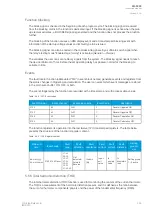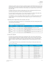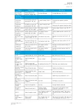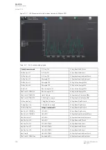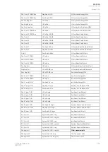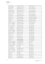
Signal
Description
Signal
Description
Neutral
susceptance B
(Pri)
Primary neutral
susceptance
f meas qlty
Quality of tracked frequency
Neutral
admittance Y (Pri)
Primary neutral admittance
f meas from
Indicates which of the three voltage or
current channel frequencies is used by the
relay.
Neutral
admittance Y
(Ang)
Neutral admittace angle
SS1.meas.frqs
Synchrocheck – the measured frequency
from voltage channel 1
I01 Resistive
component (Pri)
Primary resistive
component I01
SS2.meas.frqs
Synchrocheck – the measured frequency
from voltage channel 2
I01 Capacitive
component (Pri)
Primary capacitive
component I01
Enable f based functions
Status of this signal is active when
frequency-based protection functions are
enabled.
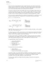
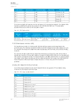
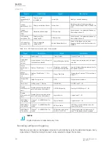
Table. 5.5.6 - 239. Digital recording channels – Binary signals.
Signal
Description
Signal
Description
DIx
Digital input 1...11
Timer x Output
Output of Timer 1...10
Open/close
control
buttons
Active if buttons I or 0 in the unit's
front panel are pressed.
Internal Relay Fault active
If the unit has an internal fault, this signal
is active.
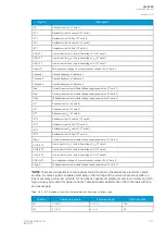
Status
PushButton x
On
Status of Push Button 1...12 is ON
(Protection, control and
monitoring event signals)
(see the individual function description for
the specific outputs)
Status
PushButton x
Off
Status of Push Button 1...12 is
OFF
Always True/False
"Always false" is always "0". Always true is
always "1".
Forced SG in
use
Stage forcing in use
OUTx
Output contact statuses
SGx Active
Setting group 1...8 active
GOOSE INx
GOOSE input 1...64
Double
Ethernet LinkA
down
Double ethernet communication
card link A connection is down.
GOOSE INx quality
Quality of GOOSE input 1...64
Double
Ethernet LinkB
down
Double ethernet communication
card link B connection is down.
Logical Input x
Logical input 1...32
MBIO ModA
Ch x Invalid
Channel 1...8 of MBIO Mod A is
invalid
Logical Output x
Logical output 1...64
MBIO ModB
Ch x Invalid
Channel 1...8 of MBIO Mod B is
invalid
NTP sync alarm
If NTP time synchronization is lost, this
signal will be active.
MBIO ModB
Ch x Invalid
Channel 1...8 of MBIO Mod C is
invalid
Ph.Rotating Logic control
0=A-B-C, 1=A-C-B
Phase rotating order at the moment. If
true ("1") the phase order is reversed.
NO
NOTE!
TE!
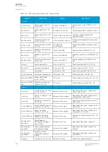
Digital channels are measured every 5 ms.
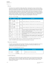
Recording settings and triggering
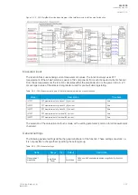
Disturbance recorder can be triggered manually or automatically by using the dedicated triggers. Every
signal listed in "Digital recording channels" can be selected to trigger the recorder.
A
AQ
Q-F205
-F205
Instruction manual
Version: 2.04
344
© Arcteq Relays Ltd
IM00013
Summary of Contents for AQ F205
Page 1: ...AQ F205 Feeder protection IED Instruction manual ...
Page 2: ......

