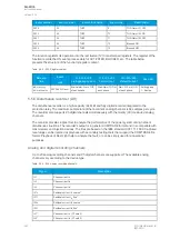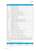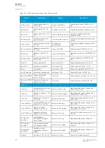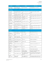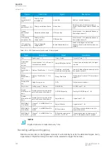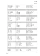
Res.Curr.angle I01
System Volt UL2 mag
TM> Reference T curr.
Res.Curr.angle I02
System Volt UL2 mag (kV)
TM> Active meas curr.
Calc.I0.angle
System Volt UL3 mag
TM> T est.with act. curr.
Pos.Seq.Curr.angle
System Volt UL3 mag (kV)
TM> T at the moment
Neg.Seq.Curr.angle
System Volt U0 mag
TM> Max.Temp.Rise All.
Zero.Seq.Curr.angle
System Volt U0 mag (kV)
TM> Temp.Rise atm.
Pri.Pha.Curr.I”L1
System Volt U1 mag
TM> Hot Spot estimate
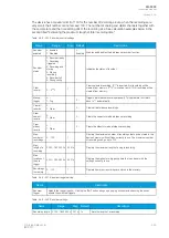
Pri.Pha.Curr.I”L2
System Volt U1 mag (kV)
TM> Hot Spot Max. All
Pri.Pha.Curr.I”L3
System Volt U2 mag
TM> Used k for amb.temp
Pri.Res.Curr.I”01
System Volt U2 mag (kV)
TM> Trip delay remaining
Pri.Res.Curr.I”02
System Volt U3 mag
TM> Alarm 1 time to rel.
Pri.Calc.I”0
System Volt U3 mag (kV)
TM> Alarm 2 time to rel.
Pha.Curr.I”L1 TRMS Pri
System Volt U4 mag
TM> Inhibit time to rel.
Pha.Curr.I”L2 TRMS Pri
System Volt U4 mag (kV)
TM> Trip time to rel.
Pha.Curr.I”L3 TRMS Pri
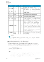
System Volt UL12 ang
S1 Measurement
I” Pri.Pos.Seq.Curr.
System Volt UL23 ang
S2 Measurement
I” Pri.Neg.Seq.Curr.
System Volt UL31 ang
S3 Measurement
I” Pri.Zero.Seq.Curr.
System Volt UL1 ang
S4 Measurement
Res.Curr.I”01 TRMS Pri
System Volt UL2 ang
S5 Measurement
Res.Curr.I”02 TRMS Pri
System Volt UL3 ang
S6 Measurement
Sec.Pha.Curr.I”L1
System Volt U0 ang
S7 Measurement
Sec.Pha.Curr.I”L2
System Volt U1 ang
S8 Measurement
Sec.Pha.Curr.I”L3
System Volt U2 ang
S9 Measurement
Sec.Res.Curr.I”01
System Volt U3 ang
S10 Measurement
Sec.Res.Curr.I”02
System Volt U4 ang
S11 Measurement
Sec.Calc.I”0
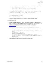
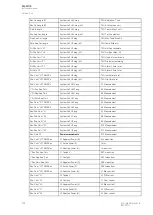
PPoow
wer mea
er measur
surements
ements
S12 Measurement
Pha.Curr.I”L1 TRMS Sec
L1 Apparent Power (S)
Sys.meas.frqs
Pha.Curr.I”L2 TRMS Sec
L1 Active Power (P)
f atm.
Pha.Curr.I”L3 TRMS Sec
L1 Reactive Power (Q)
f meas from
I” Sec.Pos.Seq.Curr.
L1 Tan(phi)
SS1.meas.frqs
I” Sec.Neg.Seq.Curr.
L1 Cos(phi)
SS1f meas from
I” Sec.Zero.Seq.Curr.
L2 Apparent Power (S)
SS2 meas.frqs
Res.Curr.I”01 TRMS Sec
L2 Active Power (P)
SS2f meas from
Res.Curr.I”02 TRMS Sec
L2 Reactive Power (Q)
L1 Bias current
Pha.Curr.I”L1
L2 Tan(phi)
L1 Diff current
Pha.Curr.I”L2
L2 Cos(phi)
L1 Char current
Pha.Curr.I”L3
L3 Apparent Power (S)
L2 Bias current
Res.Curr.I”01
L3 Active Power (P)
L2 Diff current
Res.Curr.I”02
L3 Reactive Power (Q)
L2 Char current
A
AQ
Q-F205
-F205
Instruction manual
Version: 2.04
354
© Arcteq Relays Ltd
IM00013
Summary of Contents for AQ F205
Page 1: ...AQ F205 Feeder protection IED Instruction manual ...
Page 2: ......

