Name
Range
Step Default
Description
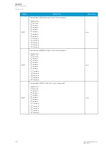
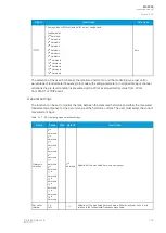
Actmode
0: Current
only
1: DO only
2: Signals
only
3: Current
and DO
4: Current or
DO
5: Current
and signals
6: Current or
signals
7: Signals
and DO
8: Signals or
DO
9: Current or
DO or
signals
10: Current
and DO and
Signals
-
0:
Current
only
Selects the operating mode. The mode can be dependent on current
measurement, binary signal status, output relay status ("DO"), or a combination
of the three.
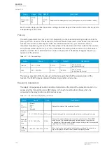
Table. 5.3.8 - 90. Pick-up settings.
Name
Range
Step
Default
Description
I
set
0.01…40.00×I
n
0.01×I
n
0.20×I
n
The pick-up threshold for the phase current measurement. This setting
limit defines the upper limit for the phase current pick-up element.
I0
set
0.005...40.000×I
n
0.001×I
n
1.200×I
n
The pick-up threshold for the residual current measurement. This setting
limit defines the upper limit for the phase current pick-up element.
The pick-up activation of the function is not directly equal to the START signal generation of the
function. The START signal is allowed if the blocking condition is not active. There is no delay between
the activation of the monitored signal and the activation of the pick-up when using binary signals.
Function blocking
The block signal is checked in the beginning of each program cycle. The blocking signal is received
from the blocking matrix in the function's dedicated input. If the blocking signal is not activated when
the pick-up element activates, a START signal is generated and the function proceeds to the time
characteristics calculation.
If the blocking signal is active when the pick-up element activates, a BLOCKED signal is generated and
the function does not process the situation further. If the START function has been activated before the
blocking signal, it resets and processes the release time characteristics similarly to when the pick-up
signal is reset.
The blocking of the function causes an HMI display event and a time-stamped blocking event with
information of the startup current values and its fault type to be issued.
The blocking signal can also be tested in the commissioning phase by a software switch signal when
the relay's testing mode "Enable stage forcing" is activated (
General
→
Device).
The variables the user can set are binary signals from the system. The blocking signal needs to reach
the device minimum of 5 ms before the set operating delay has passed in order for the blocking to
activate in time.
A
AQ
Q-F205
-F205
Instruction manual
Version: 2.04
© Arcteq Relays Ltd
IM00013
145
Summary of Contents for AQ F205
Page 1: ...AQ F205 Feeder protection IED Instruction manual ...
Page 2: ......

