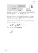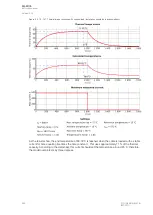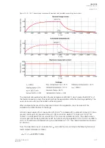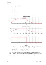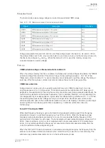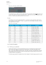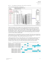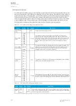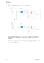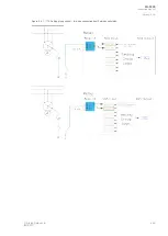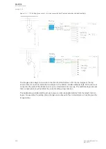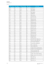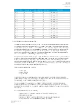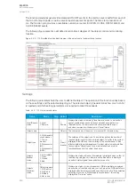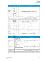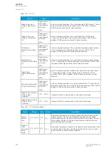
Figure. 5.3.20 - 166. Distance protection characteristics and directional overcurrent.
Voltage memory activates when the above-mentioned criteria are met. Voltage memory uses
the "VMEM activation voltage" parameter as voltage amplitude even when the actual measured voltage
has decreased below it or close to zero. The angle used by this function is the one captured
the moment before the fault occurred and voltage memory was activated. When voltage memory is
activated, the output "Voltage memory on" signal is activated. This signal can be found in the device's I/
O matrix.
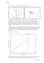
While voltage memory is active, voltages are absent and therefore angle measurement is not possible.
Healthy state angles (before a fault) are used during a fault. This is why a drift between the assumed
voltage angle and the actual measured phase current angle takes place. While voltage memory is
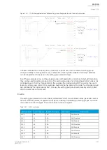
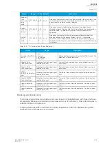
used, the angle of phase currents drifts approximately one degree for each passing second (see the
graph below).
Figure. 5.3.20 - 167. Voltage angle drift.
The blocking signal for voltage memory can be found among other stage-related settings in the tab
VT
Module (3U/4U) 1. The blocking signal is checked in the beginning of each program cycle.
A
AQ
Q-F205
-F205
Instruction manual
Version: 2.04
238
© Arcteq Relays Ltd
IM00013
Summary of Contents for AQ F205
Page 1: ...AQ F205 Feeder protection IED Instruction manual ...
Page 2: ......


