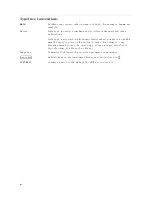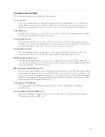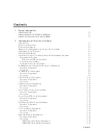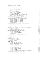
Documentation
Map
The
following
manuals
are
available
for
the
analyzer
.
User's
Guide
The
User's
Guide
walks
you
through
system
setup
and
initial
power-on,
shows
how
to
make
basic
measurements
,
explains
commonly
used
features
,
and
typical
application
measurement
examples
.
After
you
receive
your
analyzer
,
begin
with
this
manual.
T
ask
Reference
T
ask
Reference
helps
you
to
learn
how
to
use
the
analyzer
.
This
manual
provides
simple
step-by-step
instructions
without
concepts
.
Function
Reference
The
Function
Reference
describes
all
function
accessed
from
the
front
panel
keys
and
softkeys
.
It
also
provides
information
on
options
and
accessories
available
,
specications
,
system
performance
,
and
some
topics
about
the
analyzer's
features
.
Programming
Guide
The
Programming
Guide
shows
how
to
write
and
use
B
ASIC
program
to
control
the
analyzer
and
describes
how
HP
Instrument
B
ASIC
works
with
the
analyzer
..
GPIB
Command
Reference
The
GPIB
Command
Reference
provides
a
summary
of
all
available
GPIB
commands
.
It
also
provides
information
on
the
status
reporting
structure
and
the
trigger
system
(these
features
conform
to
the
SCPI
standard).
HP
Instrument
B
ASIC
Manual
Set,
The
HP
Instrument
B
ASIC
User's
Handbook
introduces
you
to
the
HP
Instrument
B
ASIC
programming
language
,
provide
some
helpful
hints
on
getting
the
most
use
from
it,
and
provide
a
general
programming
reference
.
It
is
divided
into
three
books
,
HP
Instrument
B
ASIC
Programming
T
echniques,
HP
Instrument
B
ASIC
Interface
T
echniques,
and
HP
Instrument
B
ASIC
Language
R
eference.
P
erformance
T
est
Manual
The
P
erformance
T
est
Manual
explains
how
to
verify
conformance
to
published
specications
.
Service
Manual
(Option
0B
W
only),
The
Service
Manual
explains
how
to
adjust,
troubleshoot,
and
repair
the
instrument.
This
manual
is
option
0BW
only
.
ix
Summary of Contents for Agilent 4396B
Page 10: ......
Page 32: ......
Page 43: ...Figure 2 7 CAL OUT Level Adjustment Location Adjustments and Correction Constants 2 11 ...
Page 46: ...Figure 2 10 Comb Generator Output 2 14 Adjustments and Correction Constants ...
Page 62: ...Figure 2 26 Final Gain Adjustment Location 2 30 Adjustments and Correction Constants ...
Page 76: ...Figure 3 1 Troubleshooting Organization 3 2 T roubleshooting ...
Page 84: ......
Page 90: ...Figure 5 1 Power Supply Lines Simpli ed Block Diagram 5 2 Power Supply T roubleshooting ...
Page 107: ...Figure 5 12 Power Supply Block Diagram 1 Power Supply T roubleshooting 5 19 ...
Page 108: ...Figure 5 13 Power Supply Block Diagram 2 5 20 Power Supply T roubleshooting ...
Page 109: ...Figure 5 14 Power Supply Block Diagram 3 Power Supply T roubleshooting 5 21 ...
Page 110: ......
Page 112: ...Figure 6 1 Digital Control Group Simpli ed Block Diagram 6 2 Digital Control T roubleshooting ...
Page 124: ......
Page 126: ...Figure 7 1 Source Group Block Diagram 7 2 Source Group T roubleshooting ...
Page 160: ...Figure 8 1 Receiver Group Simpli ed Block Diagram 8 2 Receiver Group T roubleshooting ...
Page 168: ......
Page 184: ...Figure 10 6 External Test Setup 1 Figure 10 7 External Test Setup 2 10 10 Service Key Menus ...
Page 185: ...Figure 10 8 External Test Setup 3 Figure 10 9 External Test Setup 4 Service Key Menus 10 11 ...
Page 226: ...Figure 11 3 Power Supply Functional Group Simpli ed Block Diagram 11 6 Theory of Operation ...
Page 231: ...Figure 11 5 Digital Control Group Simpli ed Block Diagram Theory of Operation 11 11 ...
Page 235: ...Figure 11 6 Source Simpli ed Block Diagram Theory of Operation 11 15 ...
Page 244: ...Figure 11 7 Receiver Simpli ed Block Diagram 11 24 Theory of Operation ...
Page 249: ...Figure IDC5S11001 here Figure 11 8 4396B Source Group Block Diagram Theory of Operation 11 29 ...
Page 254: ...Figure 12 1 Top View Major Assemblies 12 4 Replaceable Parts ...
Page 290: ...Figure 12 36 Main Frame Assembly Parts 17 19 12 40 Replaceable Parts ...
Page 294: ......
Page 308: ......
Page 311: ...Figure C 1 Power Cable Supplied Power Requirement C 3 ...
Page 312: ......
Page 324: ......


