


8
Receiver
Group
Troubleshooting
INTRODUCTION
Use
these
procedures
only
if
you
have
read
the
Isolate
F
aulty
Group
Troubleshooting
chapter
,
and
you
believe
the
problem
is
in
the
receiver
group
.
These
procedures
are
designed
to
let
you
identify
the
bad
assembly
within
the
receiver
group
in
the
shortest
possible
time
.
Whenever
an
assembly
is
replaced
in
this
procedure
,
refer
to
T
able
13-1
P
ost
R
epair
Procedures
in
the
P
ost-R
epair
Procedures
chapter
in
this
manual.
The
procedures
isolate
the
faulty
assembly
by
using
the
4396B
self-test
functions
(internal
and
external
tests).
In
the
external
tests
,
the
RF
OUT
signal
(which
is
the
output
of
the
source
group)
is
used
to
test
the
receiver
group
.
Therefore
,
before
performing
these
procedures
,
verify
the
source
group
.
See
the
Operator's
Check
Troubleshooting
in
the
Isolate
F
aulty
Group
chapter
.
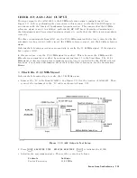
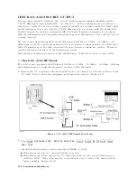
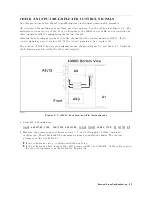
Figure
8-1
shows
a
simplied
block
diagram
of
the
receiver
group
.
The
receiver
group
consists
of
the
following
assemblies:
A8
Input
Attenuator
A9
Input
Multiplexer
A4A2
Receiver
RF
A6
Receiver
IF
Note
Make
sure
all
of
the
assemblies
listed
above
are
rmly
seated
before
performing
the
procedures
in
this
chapter
.
Allow
the
analyzer
to
warm
up
for
at
least
30
minutes
before
you
perform
any
procedure
in
this
chapter
.
Receiver
Group
T
roubleshooting
8-1
Summary of Contents for Agilent 4396B
Page 10: ......
Page 32: ......
Page 43: ...Figure 2 7 CAL OUT Level Adjustment Location Adjustments and Correction Constants 2 11 ...
Page 46: ...Figure 2 10 Comb Generator Output 2 14 Adjustments and Correction Constants ...
Page 62: ...Figure 2 26 Final Gain Adjustment Location 2 30 Adjustments and Correction Constants ...
Page 76: ...Figure 3 1 Troubleshooting Organization 3 2 T roubleshooting ...
Page 84: ......
Page 90: ...Figure 5 1 Power Supply Lines Simpli ed Block Diagram 5 2 Power Supply T roubleshooting ...
Page 107: ...Figure 5 12 Power Supply Block Diagram 1 Power Supply T roubleshooting 5 19 ...
Page 108: ...Figure 5 13 Power Supply Block Diagram 2 5 20 Power Supply T roubleshooting ...
Page 109: ...Figure 5 14 Power Supply Block Diagram 3 Power Supply T roubleshooting 5 21 ...
Page 110: ......
Page 112: ...Figure 6 1 Digital Control Group Simpli ed Block Diagram 6 2 Digital Control T roubleshooting ...
Page 124: ......
Page 126: ...Figure 7 1 Source Group Block Diagram 7 2 Source Group T roubleshooting ...
Page 160: ...Figure 8 1 Receiver Group Simpli ed Block Diagram 8 2 Receiver Group T roubleshooting ...
Page 168: ......
Page 184: ...Figure 10 6 External Test Setup 1 Figure 10 7 External Test Setup 2 10 10 Service Key Menus ...
Page 185: ...Figure 10 8 External Test Setup 3 Figure 10 9 External Test Setup 4 Service Key Menus 10 11 ...
Page 226: ...Figure 11 3 Power Supply Functional Group Simpli ed Block Diagram 11 6 Theory of Operation ...
Page 231: ...Figure 11 5 Digital Control Group Simpli ed Block Diagram Theory of Operation 11 11 ...
Page 235: ...Figure 11 6 Source Simpli ed Block Diagram Theory of Operation 11 15 ...
Page 244: ...Figure 11 7 Receiver Simpli ed Block Diagram 11 24 Theory of Operation ...
Page 249: ...Figure IDC5S11001 here Figure 11 8 4396B Source Group Block Diagram Theory of Operation 11 29 ...
Page 254: ...Figure 12 1 Top View Major Assemblies 12 4 Replaceable Parts ...
Page 290: ...Figure 12 36 Main Frame Assembly Parts 17 19 12 40 Replaceable Parts ...
Page 294: ......
Page 308: ......
Page 311: ...Figure C 1 Power Cable Supplied Power Requirement C 3 ...
Page 312: ......
Page 324: ......


