


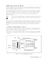


T
able
7-1.
STEP
OSC
Frequency
4396B
Center
Frequency
STEP
OSC
Frequency
Bus
Measurement
Limits
1
Hz
470
MHz
1.8359
U
6
0.01
U
80.000001
MHz
490
MHz
1.9140
U
6
0.01
U
160.000001
MHz
510
MHz
1.9921
U
6
0.01
U
240.000001
MHz
530
MHz
2.0703
U
6
0.01
U
320.000001
MHz
550
MHz
2.1484
U
6
0.01
U
400.000001
MHz
570
MHz
2.2265
U
6
0.01
U
480.000001
MHz
590
MHz
2.3046
U
6
0.01
U
560.000001
MHz
610
MHz
2.3828
U
6
0.01
U
640.000001
MHz
630
MHz
2.4609
U
6
0.01
U
720.000001
MHz
650
MHz
2.5390
U
6
0.01
U
800.000001
MHz
670
MHz
2.6171
U
6
0.01
U
880.000001
MHz
690
MHz
2.6953
U
6
0.01
U
960.000001
MHz
710
MHz
2.7734
U
6
0.01
U
1.040000001
GHz
730
MHz
2.8515
U
6
0.01
U
1.120000001
GHz
750
MHz
2.9296
U
6
0.01
U
1.200000001
GHz
770
MHz
3.0078
U
6
0.01
U
1.280000001
GHz
790
MHz
3.0859
U
6
0.01
U
1.360000001
GHz
810
MHz
3.1640
U
6
0.01
U
1.440000001
GHz
830
MHz
3.2421
U
6
0.01
U
1.520000001
GHz
850
MHz
3.3203
U
6
0.01
U
1.600000001
GHz
870
MHz
3.3984
U
6
0.01
U
1.680000001
GHz
890
MHz
3.4765
U
6
0.01
U
1.760000001
GHz
910
MHz
3.5546
U
6
0.01
U
1.819999999902
GHz
930
MHz
3.6328
U
6
0.01
U
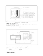
e.
On
the
spectrum
analyzer
,
press
4
PEAK
SEARCH
5
to
move
the
marker
to
the
peak
of
the
STEP
OSC
signal.
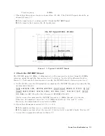
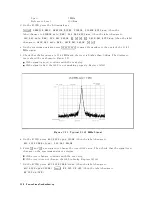
f.
P
erform
the
following
checks
to
verify
the
STEP
OSC
signal
at
a
center
frequency
of
0
Hz:
i.
Check
that
the
4396B
marker
reading
(STEP
OSC
signal
frequency)
is
1.8359
U
6
0.01
U
.
The
limits
are
listed
in
the
third
column
of
T
able
7-1.
ii.
Check
that
the
spectrum
analyzer's
marker
reading
(STEP
OSC
signal
level)
is
between
03
dBm
to
+5
dBm.
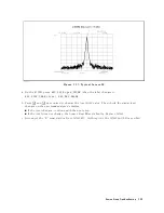
iii.
Check
that
the
trace
displayed
on
the
spectrum
analyzer
is
as
shown
in
Figure
7-12 .
If
the
signal
is
good,
continue
with
the
next
step
.
If
the
signal
is
bad,
perform
the
Comb
Generator
A
djustment
and
Step
Pretune
Correction
Constants
procedures
(see
the
A
djustments
and
Correction
Constants
chapter).
If
the
signal
is
still
bad
after
the
adjustments
are
performed,
the
STEP
OSC
is
probably
faulty
.
Replace
A5.
Source
Group
T
roubleshooting
7-15
Summary of Contents for Agilent 4396B
Page 10: ......
Page 32: ......
Page 43: ...Figure 2 7 CAL OUT Level Adjustment Location Adjustments and Correction Constants 2 11 ...
Page 46: ...Figure 2 10 Comb Generator Output 2 14 Adjustments and Correction Constants ...
Page 62: ...Figure 2 26 Final Gain Adjustment Location 2 30 Adjustments and Correction Constants ...
Page 76: ...Figure 3 1 Troubleshooting Organization 3 2 T roubleshooting ...
Page 84: ......
Page 90: ...Figure 5 1 Power Supply Lines Simpli ed Block Diagram 5 2 Power Supply T roubleshooting ...
Page 107: ...Figure 5 12 Power Supply Block Diagram 1 Power Supply T roubleshooting 5 19 ...
Page 108: ...Figure 5 13 Power Supply Block Diagram 2 5 20 Power Supply T roubleshooting ...
Page 109: ...Figure 5 14 Power Supply Block Diagram 3 Power Supply T roubleshooting 5 21 ...
Page 110: ......
Page 112: ...Figure 6 1 Digital Control Group Simpli ed Block Diagram 6 2 Digital Control T roubleshooting ...
Page 124: ......
Page 126: ...Figure 7 1 Source Group Block Diagram 7 2 Source Group T roubleshooting ...
Page 160: ...Figure 8 1 Receiver Group Simpli ed Block Diagram 8 2 Receiver Group T roubleshooting ...
Page 168: ......
Page 184: ...Figure 10 6 External Test Setup 1 Figure 10 7 External Test Setup 2 10 10 Service Key Menus ...
Page 185: ...Figure 10 8 External Test Setup 3 Figure 10 9 External Test Setup 4 Service Key Menus 10 11 ...
Page 226: ...Figure 11 3 Power Supply Functional Group Simpli ed Block Diagram 11 6 Theory of Operation ...
Page 231: ...Figure 11 5 Digital Control Group Simpli ed Block Diagram Theory of Operation 11 11 ...
Page 235: ...Figure 11 6 Source Simpli ed Block Diagram Theory of Operation 11 15 ...
Page 244: ...Figure 11 7 Receiver Simpli ed Block Diagram 11 24 Theory of Operation ...
Page 249: ...Figure IDC5S11001 here Figure 11 8 4396B Source Group Block Diagram Theory of Operation 11 29 ...
Page 254: ...Figure 12 1 Top View Major Assemblies 12 4 Replaceable Parts ...
Page 290: ...Figure 12 36 Main Frame Assembly Parts 17 19 12 40 Replaceable Parts ...
Page 294: ......
Page 308: ......
Page 311: ...Figure C 1 Power Cable Supplied Power Requirement C 3 ...
Page 312: ......
Page 324: ......


