


INSPECT
THE
PO
WER
ON
SEQUENCE
Check
the
F
an
Turn
the
analyzer
power
on.
Inspect
the
fan
on
the
rear
panel.
The
fan
should
be
rotating
and
audible
.
If
case
of
unexpected
results
,
check
A
C
line
power
to
the
analyzer
.
Check
the
fuse
(rating
listed
on
the
rear
panel).
Check
the
line
voltage
setting.
F
or
setting
the
line
voltage
,
see
the
P
ower
R
equirements
in
Appendix
C.
If
the
problem
persists
,
continue
with
the
P
ower
Supply
Troubleshooting
chapter
.
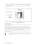
Check
the
Front
P
anel
LEDs
and
Displays
Turn
on
the
analyzer
and
watch
for
the
following
events
in
this
order:
1.
Beep
is
sounding.
2.
The
4
Ch
1
5
LED
turns
on
and
the
analyzer
displays
Internal
T
est
In
Progress
for
several
seconds
.
3.
The
analyzer
displays
the
graticule
.
If
case
of
unexpected
results
,
continue
with
Digital
Control
Troubleshooting
chapter
.
Check
Error
Message
Turn
the
analyzer
power
on.
Inspect
the
LCD
.
No
error
message
should
be
displayed.
If
one
of
the
error
message
or
a
status
annotation
listed
below
appears
on
the
LCD
,
continue
with
the
Digital
Control
Troubleshooting
chapter
.
POWER
ON
TEST
FAILED
Svc
(Status
annotation)
These
error
messages
indicate
that
one
of
power-on
self
tests
fails
.
If
an
other
error
message
appears
,
refer
to
the
Error
Messages
in
Messages
.
If
the
response
of
front
panel,
GPIB
commands
,
or
built-in
FDD
is
unexpected,
continue
with
the
Digital
Control
Troubleshooting
chapter
.
3-4
T
roubleshooting
Summary of Contents for Agilent 4396B
Page 10: ......
Page 32: ......
Page 43: ...Figure 2 7 CAL OUT Level Adjustment Location Adjustments and Correction Constants 2 11 ...
Page 46: ...Figure 2 10 Comb Generator Output 2 14 Adjustments and Correction Constants ...
Page 62: ...Figure 2 26 Final Gain Adjustment Location 2 30 Adjustments and Correction Constants ...
Page 76: ...Figure 3 1 Troubleshooting Organization 3 2 T roubleshooting ...
Page 84: ......
Page 90: ...Figure 5 1 Power Supply Lines Simpli ed Block Diagram 5 2 Power Supply T roubleshooting ...
Page 107: ...Figure 5 12 Power Supply Block Diagram 1 Power Supply T roubleshooting 5 19 ...
Page 108: ...Figure 5 13 Power Supply Block Diagram 2 5 20 Power Supply T roubleshooting ...
Page 109: ...Figure 5 14 Power Supply Block Diagram 3 Power Supply T roubleshooting 5 21 ...
Page 110: ......
Page 112: ...Figure 6 1 Digital Control Group Simpli ed Block Diagram 6 2 Digital Control T roubleshooting ...
Page 124: ......
Page 126: ...Figure 7 1 Source Group Block Diagram 7 2 Source Group T roubleshooting ...
Page 160: ...Figure 8 1 Receiver Group Simpli ed Block Diagram 8 2 Receiver Group T roubleshooting ...
Page 168: ......
Page 184: ...Figure 10 6 External Test Setup 1 Figure 10 7 External Test Setup 2 10 10 Service Key Menus ...
Page 185: ...Figure 10 8 External Test Setup 3 Figure 10 9 External Test Setup 4 Service Key Menus 10 11 ...
Page 226: ...Figure 11 3 Power Supply Functional Group Simpli ed Block Diagram 11 6 Theory of Operation ...
Page 231: ...Figure 11 5 Digital Control Group Simpli ed Block Diagram Theory of Operation 11 11 ...
Page 235: ...Figure 11 6 Source Simpli ed Block Diagram Theory of Operation 11 15 ...
Page 244: ...Figure 11 7 Receiver Simpli ed Block Diagram 11 24 Theory of Operation ...
Page 249: ...Figure IDC5S11001 here Figure 11 8 4396B Source Group Block Diagram Theory of Operation 11 29 ...
Page 254: ...Figure 12 1 Top View Major Assemblies 12 4 Replaceable Parts ...
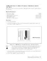
Page 290: ...Figure 12 36 Main Frame Assembly Parts 17 19 12 40 Replaceable Parts ...
Page 294: ......
Page 308: ......
Page 311: ...Figure C 1 Power Cable Supplied Power Requirement C 3 ...
Page 312: ......
Page 324: ......


