


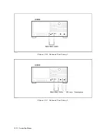


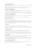


External
test
setup
5
(shown
in
Figure
10-10)
is
used
in
this
test.
The
test
measures
the
CAL
OUT
signal
using
the
S
input
to
evaluate
the
frequency
response
over
the
3
dB
passband
of
the
crystal
bandpass
lter
.
N
NNNNNNNNNNNNNNNNNNNNNNNNNNNNNNNNNNNNNNNNNNNNNNNNNNNNNN
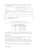
ADJUSTMENT
TESTS
This
group
of
tests
is
used
when
adjusting
the
analyzer
.
These
tests
make
the
adjustment
procedure
easier
.
F
or
more
detailed
operating
information,
see
the
A
djustments
and
Correction
Constants
chapter
.
41:
DC
OFFST/HLD
STEP
ADJ
Used
when
the
DC
Oset/Hold
Step
A
djustment
on
the
A6
receiver
IF
is
performed.
42:
0/90
DEG
TRA
CKING
ADJ
Used
when
the
0
/90
Tracking
A
djustment
on
the
A6
receiver
IF
is
performed.
43:
FINAL
GAIN
ADJ
Used
when
the
Final
Gain
A
djustment
on
the
A6
receiver
IF
is
performed.
44:
2nd
LO
PLL
LOCK
ADJ
Used
when
the
Second
Local
PLL
Lock
A
djustment
on
the
A3A2
2nd
LO
is
performed.
45:
SOURCE
MIXER
LEAK
ADJ
Used
when
the
Source
Mixer
Local
Leakage
A
djustment
on
the
A3A2
2nd
LO
is
performed.
46:
3
MHZ
BPF
ADJ
Used
when
the
Band
P
ass
Filters
A
djustment
on
the
A6
receiver
IF
is
performed.
47:
1
MHZ
BPF
ADJ
Used
when
the
Band
P
ass
Filters
A
djustment
on
the
A6
receiver
IF
is
performed.
N
NNNNNNNNNNNNNNNNNNNNNNNNNNNNNNNNNNNNNNNNNNNN
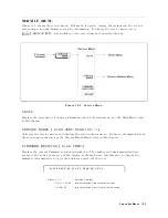
DISPLAY
TESTS
These
tests
are
test
patterns
that
are
used
in
the
factory
for
display
adjustments
,
diagnostics
,
and
troubleshooting.
They
are
not
used
for
eld
service
.
T
est
patterns
are
executed
by
entering
the
test
number
(48
through
62),
then
pressing
NNNNNNNNNNNNNNNNNNNNNNNNNNNNNNNNNNNNNN
EXECUTE
TEST
,
NNNNNNNNNNNNNNNNNNNNNNNNNN
CONTINUE
.
The
test
pattern
is
displayed
and
the
softkey
labels
are
blanked.
T
o
exit
the
test
pattern
and
return
to
the
softkey
labels
,
press
softkey
8
(on
the
bottom).
The
following
is
a
description
of
the
test
patterns
.
Note
Do
NOT
press
any
keys
except
softkey
8
(on
the
bottom)
while
the
test
pattern
is
being
executed.
If
you
do
,
you
CANNOT
quit
the
test
pattern
(that
is
,
you
can
quit
the
test
pattern
only
when
the
analyzer
is
turned
OFF).
48:
TEST
P
A
TTERN
1
All
Black.
This
pattern
is
used
to
verify
the
color
purity
of
the
LCD
Display
.
10-16
Service
K
ey
Menus
Summary of Contents for Agilent 4396B
Page 10: ......
Page 32: ......
Page 43: ...Figure 2 7 CAL OUT Level Adjustment Location Adjustments and Correction Constants 2 11 ...
Page 46: ...Figure 2 10 Comb Generator Output 2 14 Adjustments and Correction Constants ...
Page 62: ...Figure 2 26 Final Gain Adjustment Location 2 30 Adjustments and Correction Constants ...
Page 76: ...Figure 3 1 Troubleshooting Organization 3 2 T roubleshooting ...
Page 84: ......
Page 90: ...Figure 5 1 Power Supply Lines Simpli ed Block Diagram 5 2 Power Supply T roubleshooting ...
Page 107: ...Figure 5 12 Power Supply Block Diagram 1 Power Supply T roubleshooting 5 19 ...
Page 108: ...Figure 5 13 Power Supply Block Diagram 2 5 20 Power Supply T roubleshooting ...
Page 109: ...Figure 5 14 Power Supply Block Diagram 3 Power Supply T roubleshooting 5 21 ...
Page 110: ......
Page 112: ...Figure 6 1 Digital Control Group Simpli ed Block Diagram 6 2 Digital Control T roubleshooting ...
Page 124: ......
Page 126: ...Figure 7 1 Source Group Block Diagram 7 2 Source Group T roubleshooting ...
Page 160: ...Figure 8 1 Receiver Group Simpli ed Block Diagram 8 2 Receiver Group T roubleshooting ...
Page 168: ......
Page 184: ...Figure 10 6 External Test Setup 1 Figure 10 7 External Test Setup 2 10 10 Service Key Menus ...
Page 185: ...Figure 10 8 External Test Setup 3 Figure 10 9 External Test Setup 4 Service Key Menus 10 11 ...
Page 226: ...Figure 11 3 Power Supply Functional Group Simpli ed Block Diagram 11 6 Theory of Operation ...
Page 231: ...Figure 11 5 Digital Control Group Simpli ed Block Diagram Theory of Operation 11 11 ...
Page 235: ...Figure 11 6 Source Simpli ed Block Diagram Theory of Operation 11 15 ...
Page 244: ...Figure 11 7 Receiver Simpli ed Block Diagram 11 24 Theory of Operation ...
Page 249: ...Figure IDC5S11001 here Figure 11 8 4396B Source Group Block Diagram Theory of Operation 11 29 ...
Page 254: ...Figure 12 1 Top View Major Assemblies 12 4 Replaceable Parts ...
Page 290: ...Figure 12 36 Main Frame Assembly Parts 17 19 12 40 Replaceable Parts ...
Page 294: ......
Page 308: ......
Page 311: ...Figure C 1 Power Cable Supplied Power Requirement C 3 ...
Page 312: ......
Page 324: ......


