


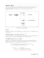


INSPECT
THE
CONNECTORS
Check
the
physical
condition
of
the
analyzer
front-panel
connectors
,
the
calibration
kit
devices
,
and
the
test
set
connectors
.
1.
Inspect
the
front
panel
connectors
on
the
analyzer
.
Check
for
bent
or
broken
center
pins
and
loose
connector
bulkheads
.
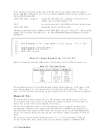
Gage
the
connectors
.
(Gage
kit
is
Agilent
part
number
85054-80011.)
The
specied
front-panel
type-N
connector
center
pin
protrusion
is
0.201
to
0.207
inch.
If
the
center
pin
protrusion
is
incorrect,
replace
the
entire
connector
assembly
,
S
input
assembly
,
or
A9
input
multiplexer
.
See
the
R
eplaceable
P
arts
chapter
.
2.
Inspect
the
calibration
kit
devices
for
bent
or
broken
center
conductors
and
other
physical
damage
.
Gage
each
device
.
The
mechanical
specications
for
each
device
are
given
in
the
calibration
kit
manual.
If
any
calibration
device
is
out
of
mechanical
tolerance
,
replace
the
device
.
3.
Inspect
and
the
gage
test
set
and
the
power
splitter
connectors
as
described
in
steps
1
and
2.
Accessories
T
roubleshooting
9-3
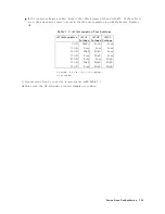
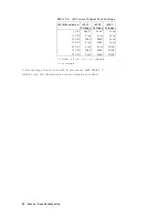
Summary of Contents for Agilent 4396B
Page 10: ......
Page 32: ......
Page 43: ...Figure 2 7 CAL OUT Level Adjustment Location Adjustments and Correction Constants 2 11 ...
Page 46: ...Figure 2 10 Comb Generator Output 2 14 Adjustments and Correction Constants ...
Page 62: ...Figure 2 26 Final Gain Adjustment Location 2 30 Adjustments and Correction Constants ...
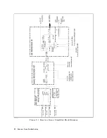
Page 76: ...Figure 3 1 Troubleshooting Organization 3 2 T roubleshooting ...
Page 84: ......
Page 90: ...Figure 5 1 Power Supply Lines Simpli ed Block Diagram 5 2 Power Supply T roubleshooting ...
Page 107: ...Figure 5 12 Power Supply Block Diagram 1 Power Supply T roubleshooting 5 19 ...
Page 108: ...Figure 5 13 Power Supply Block Diagram 2 5 20 Power Supply T roubleshooting ...
Page 109: ...Figure 5 14 Power Supply Block Diagram 3 Power Supply T roubleshooting 5 21 ...
Page 110: ......
Page 112: ...Figure 6 1 Digital Control Group Simpli ed Block Diagram 6 2 Digital Control T roubleshooting ...
Page 124: ......
Page 126: ...Figure 7 1 Source Group Block Diagram 7 2 Source Group T roubleshooting ...
Page 160: ...Figure 8 1 Receiver Group Simpli ed Block Diagram 8 2 Receiver Group T roubleshooting ...
Page 168: ......
Page 184: ...Figure 10 6 External Test Setup 1 Figure 10 7 External Test Setup 2 10 10 Service Key Menus ...
Page 185: ...Figure 10 8 External Test Setup 3 Figure 10 9 External Test Setup 4 Service Key Menus 10 11 ...
Page 226: ...Figure 11 3 Power Supply Functional Group Simpli ed Block Diagram 11 6 Theory of Operation ...
Page 231: ...Figure 11 5 Digital Control Group Simpli ed Block Diagram Theory of Operation 11 11 ...
Page 235: ...Figure 11 6 Source Simpli ed Block Diagram Theory of Operation 11 15 ...
Page 244: ...Figure 11 7 Receiver Simpli ed Block Diagram 11 24 Theory of Operation ...
Page 249: ...Figure IDC5S11001 here Figure 11 8 4396B Source Group Block Diagram Theory of Operation 11 29 ...
Page 254: ...Figure 12 1 Top View Major Assemblies 12 4 Replaceable Parts ...
Page 290: ...Figure 12 36 Main Frame Assembly Parts 17 19 12 40 Replaceable Parts ...
Page 294: ......
Page 308: ......
Page 311: ...Figure C 1 Power Cable Supplied Power Requirement C 3 ...
Page 312: ......
Page 324: ......


