


49:
TEST
P
A
TTERN
2
All
White
.
This
pattern
is
used
to
verify
the
light
output
and
to
check
the
color
purity
of
the
LCD
display
.
50:
TEST
P
A
TTERN
3
All
Red.
This
pattern
has
the
same
use
as
TEST
P
A
TTERN
2.
51:
TEST
P
A
TTERN
4
All
Green.
This
pattern
has
the
same
use
as
TEST
P
A
TTERN
2.
52:
TEST
P
A
TTERN
5
All
Blue
.
This
pattern
has
the
same
use
as
TEST
P
A
TTERN
2.
N
NNNNNNNNNNNNNNNNNNNNNNNNNNNNNNNNNNNNNNNNNNNN
ALL
EXT
TESTS
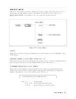
The
ALL
EXT
tests
execute
a
group
of
external
tests
.
External
tests
19
through
40
are
divided
by
the
test
setup
into
ve
groups
.
When
an
ALL
EXT
test
is
executed,
external
tests
included
in
a
group
are
sequentially
executed.
The
ALL
EXT
tests
are
used
in
the
Operator's
Check
in
the
Troubleshooting
chapter
.
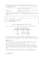
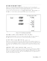
53:
ALL
EXT
1
This
test
executes
all
external
tests
that
require
external
test
setup
1
(shown
in
Figure
10-6).
This
consists
of
external
tests
21
through
27.
If
any
of
the
tests
fail,
the
test
displays
a
\F
AIL"
status
indication.
Use
the
RPG
knob
to
scroll
through
tests
21
to
27
to
see
what
test
failed.
If
all
tests
pass
,
the
test
displays
a
\P
ASS"
status
indication.
Each
test
retains
its
own
test
status
.
54:
ALL
EXT
2
This
test
executes
all
external
tests
that
require
external
test
setup
2
(shown
in
Figure
10-7).
This
test
consists
of
external
tests
19,
20,
and
28
through
31.
If
any
of
the
tests
fail,
this
test
displays
a
\F
AIL"
status
indication.
Use
the
RPG
knob
to
scroll
through
tests
19,
20,
and
28
to
31
to
see
what
test
failed.
If
all
tests
pass
,
the
test
displays
a
\P
ASS"
status
indication.
Each
test
retains
its
own
test
status
.
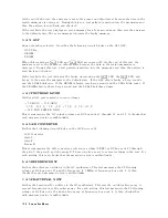
55:
ALL
EXT
3
This
test
executes
all
external
tests
that
require
external
test
setup
3
(shown
in
Figure
10-8).
This
test
consists
of
external
tests
32
and
33.
If
any
of
the
tests
fail,
this
test
displays
a
\F
AIL"
status
indication.
Use
the
RPG
knob
to
scroll
through
tests
32
to
33
to
see
what
test
failed.
If
all
tests
pass
,
the
test
displays
a
\P
ASS"
status
indication.
Each
test
retains
its
own
test
status
.
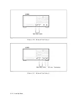
56:
ALL
EXT
4
This
test
executes
all
external
tests
that
require
external
test
setup
4
(shown
in
Figure
10-9).
This
test
consists
of
external
tests
34
and
35.
If
any
of
the
tests
fail,
this
test
displays
a
\F
AIL"
status
indication.
Use
the
RPG
knob
to
scroll
through
tests
34
to
35
to
see
what
test
failed.
If
all
tests
pass
,
the
test
displays
a
\P
ASS"
status
indication.
Each
test
retains
its
own
test
status
.
57:
ALL
EXT
5
This
test
executes
all
external
tests
that
require
external
test
setup
5
(shown
in
Figure
10-10).
This
test
consists
of
external
tests
36
through
40.
If
any
of
the
tests
fail,
the
test
displays
a
\F
AIL"
status
indication.
Use
the
RPG
knob
to
scroll
through
tests
35
to
40
to
see
what
test
failed.
If
all
tests
pass
,
the
test
displays
a
\P
ASS"
status
indication.
Each
test
retains
its
own
test
status
.
Service
K
ey
Menus
10-17
Summary of Contents for Agilent 4396B
Page 10: ......
Page 32: ......
Page 43: ...Figure 2 7 CAL OUT Level Adjustment Location Adjustments and Correction Constants 2 11 ...
Page 46: ...Figure 2 10 Comb Generator Output 2 14 Adjustments and Correction Constants ...
Page 62: ...Figure 2 26 Final Gain Adjustment Location 2 30 Adjustments and Correction Constants ...
Page 76: ...Figure 3 1 Troubleshooting Organization 3 2 T roubleshooting ...
Page 84: ......
Page 90: ...Figure 5 1 Power Supply Lines Simpli ed Block Diagram 5 2 Power Supply T roubleshooting ...
Page 107: ...Figure 5 12 Power Supply Block Diagram 1 Power Supply T roubleshooting 5 19 ...
Page 108: ...Figure 5 13 Power Supply Block Diagram 2 5 20 Power Supply T roubleshooting ...
Page 109: ...Figure 5 14 Power Supply Block Diagram 3 Power Supply T roubleshooting 5 21 ...
Page 110: ......
Page 112: ...Figure 6 1 Digital Control Group Simpli ed Block Diagram 6 2 Digital Control T roubleshooting ...
Page 124: ......
Page 126: ...Figure 7 1 Source Group Block Diagram 7 2 Source Group T roubleshooting ...
Page 160: ...Figure 8 1 Receiver Group Simpli ed Block Diagram 8 2 Receiver Group T roubleshooting ...
Page 168: ......
Page 184: ...Figure 10 6 External Test Setup 1 Figure 10 7 External Test Setup 2 10 10 Service Key Menus ...
Page 185: ...Figure 10 8 External Test Setup 3 Figure 10 9 External Test Setup 4 Service Key Menus 10 11 ...
Page 226: ...Figure 11 3 Power Supply Functional Group Simpli ed Block Diagram 11 6 Theory of Operation ...
Page 231: ...Figure 11 5 Digital Control Group Simpli ed Block Diagram Theory of Operation 11 11 ...
Page 235: ...Figure 11 6 Source Simpli ed Block Diagram Theory of Operation 11 15 ...
Page 244: ...Figure 11 7 Receiver Simpli ed Block Diagram 11 24 Theory of Operation ...
Page 249: ...Figure IDC5S11001 here Figure 11 8 4396B Source Group Block Diagram Theory of Operation 11 29 ...
Page 254: ...Figure 12 1 Top View Major Assemblies 12 4 Replaceable Parts ...
Page 290: ...Figure 12 36 Main Frame Assembly Parts 17 19 12 40 Replaceable Parts ...
Page 294: ......
Page 308: ......
Page 311: ...Figure C 1 Power Cable Supplied Power Requirement C 3 ...
Page 312: ......
Page 324: ......


