


T
able
13-1.
P
ost
Repair
Procedures
(continued)
Replaced
Assembly
or
P
art
A
djustments
Correction
Constants
(CC)
V
erication
A7
Output
Attenuator
RF
OUT
Level
CC
INSPECT
THE
PO
WER
ON
SEQUENCE
1
OPERA
TOR'S
CHECK
1
Source
Level
A
ccuracy/Flatness
Non-Sweep
P
ower
Linearity
A8
Input
Attenuator
Final
Gain
INSPECT
THE
PO
WER
ON
SEQUENCE
1
Spectrum
Analyzer
Absolute
Magnitude
CC
OPERA
TOR'S
CHECK
1
Input
Attenuator
Switching
Uncertainty
Frequency
Response
A9
Input
Multiplexer
Spectrum
Analyzer
Absolute
Magnitude
CC
INSPECT
THE
PO
WER
ON
SEQUENCE
1
Network
Analyzer
Absolute
Magnitude
CC
OPERA
TOR'S
CHECK
1
Network
Analyzer
Magnitude
Ratio/Phase
CC
Receiver
Noise
Level
Input
Crosstalk
Input
Impedance
Absolute
Amplitude
A
ccuracy
Magnitude
Ratio/Phase
Dynamic
A
ccuracy
Magnitude
Ratio/Phase
Frequency
Response
A20
MOTHERBO
ARD
None
INSPECT
THE
PO
WER
ON
SEQUENCE
1
OPERA
TOR'S
CHECK
1
A30
Keyboard
None
INSPECT
THE
PO
WER
ON
SEQUENCE
1
External
T
est
17:
FRONT
P
ANEL
DIA
G.
2
A31
I/O
Connector
None
INSPECT
THE
PO
WER
ON
SEQUENCE
1
None
TROUBLESHOO
T
GPIB
SY
STEM
1
Inspect
the
T
est
Set
3
A32
I-B
ASIC
Interface
None
INSPECT
THE
PO
WER
ON
SEQUENCE
1
None
Check
the
A32
I-B
ASIC
Interface
and
mini
DIN
K
ey
board
4
A40
Pre-Regulator
None
Internal
T
est
4:
A2
POST
REGULA
TOR
5
A51
GSP
Display
Background
INSPECT
THE
PO
WER
ON
SEQUENCE
1
A52
LCD
None
INSPECT
THE
PO
WER
ON
SEQUENCE
1
A53
FDD
None
INSPECT
THE
PO
WER
ON
SEQUENCE
1
External
T
est
18:
DSK
DR
F
A
UL
TY
ISOLN
5
A60
High
Stability
10
MHz
Reference
Oscillator
Frequency
INSPECT
THE
PO
WER
ON
SEQUENCE
1
Frequency
Reference
Frequency
A
ccuracy
1
See
the
Troubleshooting
chapter
.
2
See
the
Service
K
ey
Menus
chapter
.
3
See
the
A
ccessories
Troubleshooting
chapter
.
4
See
the
Digital
Control
Troubleshooting
chapter
.
5
See
the
Service
K
ey
Menus
chapter
.
13-4
P
ost
Repair
Procedures
Summary of Contents for Agilent 4396B
Page 10: ......
Page 32: ......
Page 43: ...Figure 2 7 CAL OUT Level Adjustment Location Adjustments and Correction Constants 2 11 ...
Page 46: ...Figure 2 10 Comb Generator Output 2 14 Adjustments and Correction Constants ...
Page 62: ...Figure 2 26 Final Gain Adjustment Location 2 30 Adjustments and Correction Constants ...
Page 76: ...Figure 3 1 Troubleshooting Organization 3 2 T roubleshooting ...
Page 84: ......
Page 90: ...Figure 5 1 Power Supply Lines Simpli ed Block Diagram 5 2 Power Supply T roubleshooting ...
Page 107: ...Figure 5 12 Power Supply Block Diagram 1 Power Supply T roubleshooting 5 19 ...
Page 108: ...Figure 5 13 Power Supply Block Diagram 2 5 20 Power Supply T roubleshooting ...
Page 109: ...Figure 5 14 Power Supply Block Diagram 3 Power Supply T roubleshooting 5 21 ...
Page 110: ......
Page 112: ...Figure 6 1 Digital Control Group Simpli ed Block Diagram 6 2 Digital Control T roubleshooting ...
Page 124: ......
Page 126: ...Figure 7 1 Source Group Block Diagram 7 2 Source Group T roubleshooting ...
Page 160: ...Figure 8 1 Receiver Group Simpli ed Block Diagram 8 2 Receiver Group T roubleshooting ...
Page 168: ......
Page 184: ...Figure 10 6 External Test Setup 1 Figure 10 7 External Test Setup 2 10 10 Service Key Menus ...
Page 185: ...Figure 10 8 External Test Setup 3 Figure 10 9 External Test Setup 4 Service Key Menus 10 11 ...
Page 226: ...Figure 11 3 Power Supply Functional Group Simpli ed Block Diagram 11 6 Theory of Operation ...
Page 231: ...Figure 11 5 Digital Control Group Simpli ed Block Diagram Theory of Operation 11 11 ...
Page 235: ...Figure 11 6 Source Simpli ed Block Diagram Theory of Operation 11 15 ...
Page 244: ...Figure 11 7 Receiver Simpli ed Block Diagram 11 24 Theory of Operation ...
Page 249: ...Figure IDC5S11001 here Figure 11 8 4396B Source Group Block Diagram Theory of Operation 11 29 ...
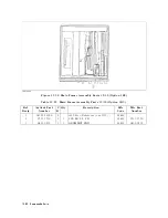
Page 254: ...Figure 12 1 Top View Major Assemblies 12 4 Replaceable Parts ...
Page 290: ...Figure 12 36 Main Frame Assembly Parts 17 19 12 40 Replaceable Parts ...
Page 294: ......
Page 308: ......
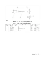
Page 311: ...Figure C 1 Power Cable Supplied Power Requirement C 3 ...
Page 312: ......
Page 324: ......


