


T
ables
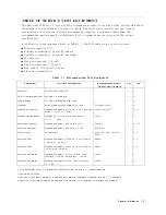
1-1.
Recommended
T
est
Equipment
.
.
.
.
.
.
.
.
.
.
.
.
.
.
.
.
.
.
.
.
.
.
.
1-3
2-1.
Required
Binaries
.
.
.
.
.
.
.
.
.
.
.
.
.
.
.
.
.
.
.
.
.
.
.
.
.
.
.
.
.
2-4
4-1.
Functional
Group
to
Suspect
When
a
P
erformance
T
est
F
ails
.
.
.
.
.
.
.
.
.
4-4
5-1.
A50
P
ower
Supplies
.
.
.
.
.
.
.
.
.
.
.
.
.
.
.
.
.
.
.
.
.
.
.
.
.
.
.
.
5-15
5-2.
P
ower
Supplies
on
A2
P
ost-Regulator
.
.
.
.
.
.
.
.
.
.
.
.
.
.
.
.
.
.
.
.
5-18
6-1.
Troubleshooting
Information
for
Internal
Diagnostic
T
est
F
ailure
.
.
.
.
.
.
.
6-9
7-1.
STEP
OSC
Frequency
.
.
.
.
.
.
.
.
.
.
.
.
.
.
.
.
.
.
.
.
.
.
.
.
.
.
.
7-15
7-2.
A3A3
Source
T
est
Settings
.
.
.
.
.
.
.
.
.
.
.
.
.
.
.
.
.
.
.
.
.
.
.
.
.
7-31
7-3.
A7
Attenuation
T
est
Settings
.
.
.
.
.
.
.
.
.
.
.
.
.
.
.
.
.
.
.
.
.
.
.
.
7-33
8-1.
Suspicious
Assembly
When
an
ALL
EXT
T
est
F
ails
.
.
.
.
.
.
.
.
.
.
.
.
.
.
8-4
8-2.
A8
Control
Signal
T
est
Settings
.
.
.
.
.
.
.
.
.
.
.
.
.
.
.
.
.
.
.
.
.
.
.
8-6
8-3.
A9J13
Pin
Description
.
.
.
.
.
.
.
.
.
.
.
.
.
.
.
.
.
.
.
.
.
.
.
.
.
.
.
8-8
8-4.
A9
Control
Signal
T
est
Settings
.
.
.
.
.
.
.
.
.
.
.
.
.
.
.
.
.
.
.
.
.
.
.
8-8
10-1.
T
est
Status
T
erms
.
.
.
.
.
.
.
.
.
.
.
.
.
.
.
.
.
.
.
.
.
.
.
.
.
.
.
.
.
10-6
10-2.
Typical
STEP
VTUNE
V
alues
.
.
.
.
.
.
.
.
.
.
.
.
.
.
.
.
.
.
.
.
.
.
.
.
10-27
11-1.
STEP
OSC
Frequency
.
.
.
.
.
.
.
.
.
.
.
.
.
.
.
.
.
.
.
.
.
.
.
.
.
.
.
11-17
11-2.
RF
OUT
P
ower
,
A3A3
Output,
and
A7
Attenuator
(Non-P
ower
Sweep)
.
.
.
.
11-22
11-3.
Stop
P
ower
,
A7
Attenuation,
and
Allowable
Start
P
ower
(P
ower
Sweep)
.
.
.
.
11-22
11-4.
Measurement
Setting,
Used
Filter
,
and
Sampling
Mode
.
.
.
.
.
.
.
.
.
.
.
.
11-26
11-5.
Gains
and
Ranges
Settings
.
.
.
.
.
.
.
.
.
.
.
.
.
.
.
.
.
.
.
.
.
.
.
.
.
11-28
12-1.
Manufacturers
Code
List
.
.
.
.
.
.
.
.
.
.
.
.
.
.
.
.
.
.
.
.
.
.
.
.
.
.
12-2
12-2.
List
of
Abbreviations
.
.
.
.
.
.
.
.
.
.
.
.
.
.
.
.
.
.
.
.
.
.
.
.
.
.
.
.
12-3
12-3.
T
op
View
(Major
Assemblies)
.
.
.
.
.
.
.
.
.
.
.
.
.
.
.
.
.
.
.
.
.
.
.
.
12-5
12-4.
Bottom
View
(Major
Assemblies)
.
.
.
.
.
.
.
.
.
.
.
.
.
.
.
.
.
.
.
.
.
.
12-6
12-5.
Angle
Assembly
P
arts
1/3
.
.
.
.
.
.
.
.
.
.
.
.
.
.
.
.
.
.
.
.
.
.
.
.
.
12-7
12-6.
Angle
Assembly
P
arts
2/3
.
.
.
.
.
.
.
.
.
.
.
.
.
.
.
.
.
.
.
.
.
.
.
.
.
12-8
12-7.
Angle
Assembly
P
arts
3/3
.
.
.
.
.
.
.
.
.
.
.
.
.
.
.
.
.
.
.
.
.
.
.
.
.
12-9
12-8.
A
TT
Assembly
P
arts
1/2
.
.
.
.
.
.
.
.
.
.
.
.
.
.
.
.
.
.
.
.
.
.
.
.
.
.
12-10
12-9.
A
TT
Assembly
P
arts
2/2
.
.
.
.
.
.
.
.
.
.
.
.
.
.
.
.
.
.
.
.
.
.
.
.
.
.
12-11
12-10.
Front
Assembly
P
arts
1/5
.
.
.
.
.
.
.
.
.
.
.
.
.
.
.
.
.
.
.
.
.
.
.
.
.
.
12-12
12-11.
Front
Assembly
P
arts
2/5
.
.
.
.
.
.
.
.
.
.
.
.
.
.
.
.
.
.
.
.
.
.
.
.
.
.
12-13
12-12.
Front
Assembly
P
arts
3/5
.
.
.
.
.
.
.
.
.
.
.
.
.
.
.
.
.
.
.
.
.
.
.
.
.
.
12-14
12-13.
Front
Assembly
P
arts
4/5
.
.
.
.
.
.
.
.
.
.
.
.
.
.
.
.
.
.
.
.
.
.
.
.
.
.
12-15
12-14.
Front
Assembly
P
arts
5/5
.
.
.
.
.
.
.
.
.
.
.
.
.
.
.
.
.
.
.
.
.
.
.
.
.
.
12-16
12-15.
Rear
Assembly
P
arts
1/7
.
.
.
.
.
.
.
.
.
.
.
.
.
.
.
.
.
.
.
.
.
.
.
.
.
.
12-17
12-16.
Rear
Assembly
P
arts
2/7
.
.
.
.
.
.
.
.
.
.
.
.
.
.
.
.
.
.
.
.
.
.
.
.
.
.
12-18
12-17.
Rear
Assembly
P
arts
3/7
.
.
.
.
.
.
.
.
.
.
.
.
.
.
.
.
.
.
.
.
.
.
.
.
.
.
12-19
12-18.
Rear
Assembly
P
arts
4/7
.
.
.
.
.
.
.
.
.
.
.
.
.
.
.
.
.
.
.
.
.
.
.
.
.
.
12-20
12-19.
Rear
Assembly
P
arts
5/7
.
.
.
.
.
.
.
.
.
.
.
.
.
.
.
.
.
.
.
.
.
.
.
.
.
.
12-21
12-20.
Rear
Assembly
P
arts
6/7
.
.
.
.
.
.
.
.
.
.
.
.
.
.
.
.
.
.
.
.
.
.
.
.
.
.
12-22
12-21.
Rear
Assembly
P
arts
7/7
.
.
.
.
.
.
.
.
.
.
.
.
.
.
.
.
.
.
.
.
.
.
.
.
.
.
12-23
12-22.
Main
Frame
Assembly
P
arts
1/19
(A3
Assemblies)
.
.
.
.
.
.
.
.
.
.
.
.
.
.
12-24
12-23.
Main
Frame
Assembly
P
arts
2/19
(A3
Assemblies)
.
.
.
.
.
.
.
.
.
.
.
.
.
.
12-25
12-24.
Main
Frame
Assembly
P
arts
3/19
.
.
.
.
.
.
.
.
.
.
.
.
.
.
.
.
.
.
.
.
.
.
12-26
12-25.
Main
Frame
Assembly
P
arts
4/19
(A9
Input
Multiplexer
Assembly)
.
.
.
.
.
.
12-27
12-26.
Main
Frame
Assembly
P
arts
5/19
(A
TT
&
Angle
Assemblies)
.
.
.
.
.
.
.
.
.
12-28
Contents-15
Summary of Contents for Agilent 4396B
Page 10: ......
Page 32: ......
Page 43: ...Figure 2 7 CAL OUT Level Adjustment Location Adjustments and Correction Constants 2 11 ...
Page 46: ...Figure 2 10 Comb Generator Output 2 14 Adjustments and Correction Constants ...
Page 62: ...Figure 2 26 Final Gain Adjustment Location 2 30 Adjustments and Correction Constants ...
Page 76: ...Figure 3 1 Troubleshooting Organization 3 2 T roubleshooting ...
Page 84: ......
Page 90: ...Figure 5 1 Power Supply Lines Simpli ed Block Diagram 5 2 Power Supply T roubleshooting ...
Page 107: ...Figure 5 12 Power Supply Block Diagram 1 Power Supply T roubleshooting 5 19 ...
Page 108: ...Figure 5 13 Power Supply Block Diagram 2 5 20 Power Supply T roubleshooting ...
Page 109: ...Figure 5 14 Power Supply Block Diagram 3 Power Supply T roubleshooting 5 21 ...
Page 110: ......
Page 112: ...Figure 6 1 Digital Control Group Simpli ed Block Diagram 6 2 Digital Control T roubleshooting ...
Page 124: ......
Page 126: ...Figure 7 1 Source Group Block Diagram 7 2 Source Group T roubleshooting ...
Page 160: ...Figure 8 1 Receiver Group Simpli ed Block Diagram 8 2 Receiver Group T roubleshooting ...
Page 168: ......
Page 184: ...Figure 10 6 External Test Setup 1 Figure 10 7 External Test Setup 2 10 10 Service Key Menus ...
Page 185: ...Figure 10 8 External Test Setup 3 Figure 10 9 External Test Setup 4 Service Key Menus 10 11 ...
Page 226: ...Figure 11 3 Power Supply Functional Group Simpli ed Block Diagram 11 6 Theory of Operation ...
Page 231: ...Figure 11 5 Digital Control Group Simpli ed Block Diagram Theory of Operation 11 11 ...
Page 235: ...Figure 11 6 Source Simpli ed Block Diagram Theory of Operation 11 15 ...
Page 244: ...Figure 11 7 Receiver Simpli ed Block Diagram 11 24 Theory of Operation ...
Page 249: ...Figure IDC5S11001 here Figure 11 8 4396B Source Group Block Diagram Theory of Operation 11 29 ...
Page 254: ...Figure 12 1 Top View Major Assemblies 12 4 Replaceable Parts ...
Page 290: ...Figure 12 36 Main Frame Assembly Parts 17 19 12 40 Replaceable Parts ...
Page 294: ......
Page 308: ......
Page 311: ...Figure C 1 Power Cable Supplied Power Requirement C 3 ...
Page 312: ......
Page 324: ......


