


INSPECT
THE
REAR
P
ANEL
FEA
TURE
If
the
analyzer
is
operating
unexpectedly
after
these
checks
are
veried,
continue
with
Digital
Control
Troubleshooting
chapter
.
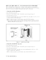
Check
the
GPIB
Interface
If
the
unexpected
operations
appear
when
controlling
the
analyzer
with
an
external
controller
,
perform
the
following
checks
to
verify
the
problem
is
not
with
the
controller
.
Compatibility
,
must
be
HP
9000
series
200/300,
see
the
manuals
of
the
controller
and
the
B
ASIC
system.
GPIB
interface
hardware
must
be
installed
in
the
controller
,
see
the
manuals
of
the
controller
and
the
B
ASIC
system.
I/O
and
GPIB
binaries
loaded,
see
the
manuals
of
the
B
ASIC
system.
Select
code
,
see
the
manuals
of
the
B
ASIC
system.
GPIB
cables
,
see
the
manuals
of
the
B
ASIC
system.
Programming
syntax,
see
the
manuals
of
the
B
ASIC
system.
Check
the
P
arallel
Interface
See
the
Printing
Out
The
Measurement
Result
at
the
Chapter
3,
Network
Analyzer
T
our
of
the
4396B
User's
Guide
,
and
make
a
hardcopy
of
the
display
.
Check
the
mini
DIN
K
eyboard
Connector
See
the
Connecting
a
Keyboard
at
the
Chapter
1,
Installation
and
Setup
guide
of
4396B
User's
Guide
and
Using
HP
Instrument
B
ASIC
with
the
4396B
.
T
roubleshooting
3-9
Summary of Contents for Agilent 4396B
Page 10: ......
Page 32: ......
Page 43: ...Figure 2 7 CAL OUT Level Adjustment Location Adjustments and Correction Constants 2 11 ...
Page 46: ...Figure 2 10 Comb Generator Output 2 14 Adjustments and Correction Constants ...
Page 62: ...Figure 2 26 Final Gain Adjustment Location 2 30 Adjustments and Correction Constants ...
Page 76: ...Figure 3 1 Troubleshooting Organization 3 2 T roubleshooting ...
Page 84: ......
Page 90: ...Figure 5 1 Power Supply Lines Simpli ed Block Diagram 5 2 Power Supply T roubleshooting ...
Page 107: ...Figure 5 12 Power Supply Block Diagram 1 Power Supply T roubleshooting 5 19 ...
Page 108: ...Figure 5 13 Power Supply Block Diagram 2 5 20 Power Supply T roubleshooting ...
Page 109: ...Figure 5 14 Power Supply Block Diagram 3 Power Supply T roubleshooting 5 21 ...
Page 110: ......
Page 112: ...Figure 6 1 Digital Control Group Simpli ed Block Diagram 6 2 Digital Control T roubleshooting ...
Page 124: ......
Page 126: ...Figure 7 1 Source Group Block Diagram 7 2 Source Group T roubleshooting ...
Page 160: ...Figure 8 1 Receiver Group Simpli ed Block Diagram 8 2 Receiver Group T roubleshooting ...
Page 168: ......
Page 184: ...Figure 10 6 External Test Setup 1 Figure 10 7 External Test Setup 2 10 10 Service Key Menus ...
Page 185: ...Figure 10 8 External Test Setup 3 Figure 10 9 External Test Setup 4 Service Key Menus 10 11 ...
Page 226: ...Figure 11 3 Power Supply Functional Group Simpli ed Block Diagram 11 6 Theory of Operation ...
Page 231: ...Figure 11 5 Digital Control Group Simpli ed Block Diagram Theory of Operation 11 11 ...
Page 235: ...Figure 11 6 Source Simpli ed Block Diagram Theory of Operation 11 15 ...
Page 244: ...Figure 11 7 Receiver Simpli ed Block Diagram 11 24 Theory of Operation ...
Page 249: ...Figure IDC5S11001 here Figure 11 8 4396B Source Group Block Diagram Theory of Operation 11 29 ...
Page 254: ...Figure 12 1 Top View Major Assemblies 12 4 Replaceable Parts ...
Page 290: ...Figure 12 36 Main Frame Assembly Parts 17 19 12 40 Replaceable Parts ...
Page 294: ......
Page 308: ......
Page 311: ...Figure C 1 Power Cable Supplied Power Requirement C 3 ...
Page 312: ......
Page 324: ......


