


3
Troubleshooting
INTRODUCTION
This
chapter
describes
overall
troubleshooting
summary
and
provides
the
procedure
to
determine
whether
the
analyzer
is
faulty
,
or
not.
The
procedure
is
performed
rst
in
the
troubleshooting
of
this
manual.
TROUBLESHOOTING
SUMMARY
The
troubleshooting
strategy
of
this
manual
is
based
on
a
verication
(rather
than
symptomatic)
approach.
This
chapter's
rst
step
is
to
verify
the
operation
of
the
analyzer
alone
,
independent
of
accessories
or
system
peripherals
.
A
ccessories
are
devices
like
test
sets
,
power
probes
,
power
splitters
,
cables
,
and
calibration
kits
.
P
eripherals
are
devices
like
computers
,
printers
,
and
keyboards
,
for
instance
,
and
which
typically
use
an
GPIB
connection
and
a
line
connection.
This
chapter
also
suggests
remedies
for
system
problems
external
to
the
analyzer
.
This
chapter
identies
one
or
some
faulty
groups
in
the
analyzer's
ve
functional
groups
.
Then
refers
the
technician
to
the
appropriate
chapter
.
The
ve
functional
groups
are
power
supply
,
digital
control,
source
,
receiver
,
and
accessories
.
Descriptions
of
these
groups
are
provided
in
the
Theory
of
Operation
chapter
.
Isolate
F
aulty
Group
Troubleshooting
,
the
next
chapter
,
assumes
that
the
fault
is
within
one
of
two
functional
groups:
source
,
receiver
.
Isolate
F
aulty
Group
Troubleshooting
identies
the
faulty
group
and
refers
the
technician
to
the
appropriate
chapter
.
These
rst
chapters
,
Troubleshooting
and
Isolate
F
aulty
Group
Troubleshooting,
stress
simple
,
straight
forward
procedures
.
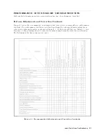
Figure
3-1
diagrams
the
troubleshooting
organization.
Each
of
the
ve
chapters
following
Isolate
F
aulty
Group
Troubleshooting
veries
,
one
at
a
time
,
the
assemblies
within
a
group
until
the
faulty
assembly
is
identied.
These
ve
chapters
employ
more
lengthy
,
complicated
procedures
.
P
ost-R
epair
Procedures,
is
the
last
chapter
of
the
troubleshooting
portion
of
the
manual.
P
ost-R
epair
Procedures
is
organized
by
assembly
and
notes
what
adjustment
to
perform
and
how
to
verify
proper
instrument
operation
following
the
replacement
of
an
assembly
.
T
roubleshooting
3-1
Summary of Contents for Agilent 4396B
Page 10: ......
Page 32: ......
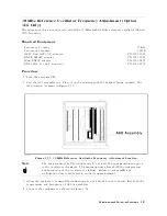
Page 43: ...Figure 2 7 CAL OUT Level Adjustment Location Adjustments and Correction Constants 2 11 ...
Page 46: ...Figure 2 10 Comb Generator Output 2 14 Adjustments and Correction Constants ...
Page 62: ...Figure 2 26 Final Gain Adjustment Location 2 30 Adjustments and Correction Constants ...
Page 76: ...Figure 3 1 Troubleshooting Organization 3 2 T roubleshooting ...
Page 84: ......
Page 90: ...Figure 5 1 Power Supply Lines Simpli ed Block Diagram 5 2 Power Supply T roubleshooting ...
Page 107: ...Figure 5 12 Power Supply Block Diagram 1 Power Supply T roubleshooting 5 19 ...
Page 108: ...Figure 5 13 Power Supply Block Diagram 2 5 20 Power Supply T roubleshooting ...
Page 109: ...Figure 5 14 Power Supply Block Diagram 3 Power Supply T roubleshooting 5 21 ...
Page 110: ......
Page 112: ...Figure 6 1 Digital Control Group Simpli ed Block Diagram 6 2 Digital Control T roubleshooting ...
Page 124: ......
Page 126: ...Figure 7 1 Source Group Block Diagram 7 2 Source Group T roubleshooting ...
Page 160: ...Figure 8 1 Receiver Group Simpli ed Block Diagram 8 2 Receiver Group T roubleshooting ...
Page 168: ......
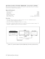
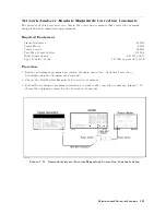
Page 184: ...Figure 10 6 External Test Setup 1 Figure 10 7 External Test Setup 2 10 10 Service Key Menus ...
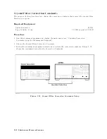
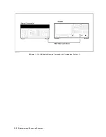
Page 185: ...Figure 10 8 External Test Setup 3 Figure 10 9 External Test Setup 4 Service Key Menus 10 11 ...
Page 226: ...Figure 11 3 Power Supply Functional Group Simpli ed Block Diagram 11 6 Theory of Operation ...
Page 231: ...Figure 11 5 Digital Control Group Simpli ed Block Diagram Theory of Operation 11 11 ...
Page 235: ...Figure 11 6 Source Simpli ed Block Diagram Theory of Operation 11 15 ...
Page 244: ...Figure 11 7 Receiver Simpli ed Block Diagram 11 24 Theory of Operation ...
Page 249: ...Figure IDC5S11001 here Figure 11 8 4396B Source Group Block Diagram Theory of Operation 11 29 ...
Page 254: ...Figure 12 1 Top View Major Assemblies 12 4 Replaceable Parts ...
Page 290: ...Figure 12 36 Main Frame Assembly Parts 17 19 12 40 Replaceable Parts ...
Page 294: ......
Page 308: ......
Page 311: ...Figure C 1 Power Cable Supplied Power Requirement C 3 ...
Page 312: ......
Page 324: ......


