


2.
Check
Error
Messages
Turn
the
analyzer
power
on.
Check
no
error
message
appears
on
the
LCD
.
If
no
error
message
is
displayed,
continue
with
the
Check
A1
DRAM
and
Flash
Memory
in
this
ST
ART
HERE.
If
one
of
error
messages
listed
below
is
displayed,
follow
the
instruction
described
below
.
F
or
the
other
message
,
see
the
Error
Messages
in
Messages
.
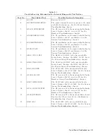
Error
Messages
Instruction
POWER
ON
TEST
FAILED
This
indicates
the
power
on
selftest
failed.
Continue
with
the
next
Check
P
ower
On
Selftest.
EEPROM
CHECK
SUM
ERROR
This
indicates
that
the
correction
constants
stored
in
the
EEPROM
on
the
A1
CPU
are
invalid
or
the
EEPROM
is
faulty
.
Rewrite
all
correction
constants
into
the
EEPROM.
F
or
the
detailed
procedure
,
See
the
A
djustments
and
Correction
Constants
chapter
in
this
manual.
If
the
rewriting
is
not
successfully
performed,
replace
the
EEPROM
and
then
rewrite
the
all
correction
constants
into
the
new
EEPROM.
Svc
(Status
Annotation)
This
indicates
that
the
correction
constants
stored
in
the
EEPROM
on
the
A1
CPU
are
invalid
or
the
EEPROM
is
faulty
.
See
the
instruction
of
the
EEPROM
CHECK
SUM
ERROR
message
.
POWER
FAILED
ON
-
-
-
One
or
some
of
A2
power
supplies
,
+15
V
,
+8.5
V
,
+5.3
V
,
+5
V
,
-5
V
,
-15
V
are
displayed
in
-
-
-
of
the
message
.
The
displayed
power
supplies
are
shut
down
due
to
the
trouble
on
the
A2
post-regulator
.
Continue
with
the
P
ower
Supply
Troubleshooting
chapter
.
POWER
FAILED
ON
PostRegHot
This
indicates
A2
power
supplies
,
+15
V
,
+8.5
V
,
+5.3
V
,
+5
V
,
-5
V
,
-15
V
,
are
shut
down
due
to
too
hot
heat
sink
on
A2
post-regulator
.
Cool
down
the
analyzer
for
about
30
minutes
.
Then
turn
the
analyzer
power
on.
If
this
message
is
still
displayed,
replace
A2
post-regulator
.
PHASE
LOCK
LOOP
UNLOCKED
This
indicates
one
or
some
of
PLLs
(phase
lock
loops)
in
the
oscillators
listed
below
is
not
working
properly
.
These
oscillators
are
checked
in
the
internal
test
0:
ALL
INT
.
Continue
with
the
next
Check
the
P
ower
On
Selftest
in
where
the
ALL
INT
test
is
executed.
Assembly
Oscillator
In
the
A5
Synthesizer
Reference
Oscillator
Step
Oscillator
In
the
A3A2
2nd
LO
2nd
LO
Oscillator
In
the
A4A1
1st
LO
1st
LO
Oscillator
In
the
A6
Receiver
IF
3rd
LO
Oscillator
Check
the
P
ower
On
Selftest
The
analyzer
performs
the
power
on
selftest
every
time
when
the
analyzer
is
turned
on.
In
the
power
on
selftest,
internal
diagnostic
tests
1,
4,
5,
6,
7,
and
9
through
16
are
executed
sequentially
.
The
rst
failed
test
indicates
the
most
probable
faulty
assembly
.
F
or
more
information
about
the
internal
tests
,
see
the
Service
Menu
K
eys
chapter
in
this
manual.
Digital
Control
T
roubleshooting
6-7
Summary of Contents for Agilent 4396B
Page 10: ......
Page 32: ......
Page 43: ...Figure 2 7 CAL OUT Level Adjustment Location Adjustments and Correction Constants 2 11 ...
Page 46: ...Figure 2 10 Comb Generator Output 2 14 Adjustments and Correction Constants ...
Page 62: ...Figure 2 26 Final Gain Adjustment Location 2 30 Adjustments and Correction Constants ...
Page 76: ...Figure 3 1 Troubleshooting Organization 3 2 T roubleshooting ...
Page 84: ......
Page 90: ...Figure 5 1 Power Supply Lines Simpli ed Block Diagram 5 2 Power Supply T roubleshooting ...
Page 107: ...Figure 5 12 Power Supply Block Diagram 1 Power Supply T roubleshooting 5 19 ...
Page 108: ...Figure 5 13 Power Supply Block Diagram 2 5 20 Power Supply T roubleshooting ...
Page 109: ...Figure 5 14 Power Supply Block Diagram 3 Power Supply T roubleshooting 5 21 ...
Page 110: ......
Page 112: ...Figure 6 1 Digital Control Group Simpli ed Block Diagram 6 2 Digital Control T roubleshooting ...
Page 124: ......
Page 126: ...Figure 7 1 Source Group Block Diagram 7 2 Source Group T roubleshooting ...
Page 160: ...Figure 8 1 Receiver Group Simpli ed Block Diagram 8 2 Receiver Group T roubleshooting ...
Page 168: ......
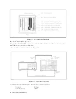
Page 184: ...Figure 10 6 External Test Setup 1 Figure 10 7 External Test Setup 2 10 10 Service Key Menus ...
Page 185: ...Figure 10 8 External Test Setup 3 Figure 10 9 External Test Setup 4 Service Key Menus 10 11 ...
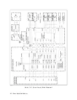
Page 226: ...Figure 11 3 Power Supply Functional Group Simpli ed Block Diagram 11 6 Theory of Operation ...
Page 231: ...Figure 11 5 Digital Control Group Simpli ed Block Diagram Theory of Operation 11 11 ...
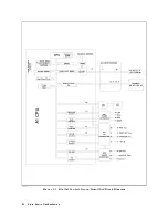
Page 235: ...Figure 11 6 Source Simpli ed Block Diagram Theory of Operation 11 15 ...
Page 244: ...Figure 11 7 Receiver Simpli ed Block Diagram 11 24 Theory of Operation ...
Page 249: ...Figure IDC5S11001 here Figure 11 8 4396B Source Group Block Diagram Theory of Operation 11 29 ...
Page 254: ...Figure 12 1 Top View Major Assemblies 12 4 Replaceable Parts ...
Page 290: ...Figure 12 36 Main Frame Assembly Parts 17 19 12 40 Replaceable Parts ...
Page 294: ......
Page 308: ......
Page 311: ...Figure C 1 Power Cable Supplied Power Requirement C 3 ...
Page 312: ......
Page 324: ......


