


Exchange
Assemblies
Under
the
rebuilt-exchange
assembly
program,
certain
factory-repaired
and
tested
assemblies
are
available
on
a
trade-in
basis
.
These
assemblies
are
oered
at
lower
cost
than
a
new
assembly
while
meeting
all
of
the
factory
specications
required
of
a
new
assembly
.
Replaceable
P
arts
List
Replaceable
parts
tables
list
the
following
information
for
each
part.
1
Agilent
T
echnologies
part
number
.
2
P
art
number
check
digit
(CD).
3
P
art
quantity
as
shown
in
the
corresponding
gure
.
There
may
or
may
not
be
more
of
the
same
part
located
elsewhere
in
the
instrument.
4
P
art
description,
using
abbreviations
(see
T
able
12-2 ).
5
A
typical
manufacturer
of
the
part
in
a
ve-digit
code
(see
T
able
12-1 ).
6
The
manufacturer's
part
number
.
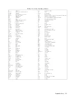
T
able
12-1.
Manufacturers
Code
List
Mfr
#
Name
Location
Zipcode
00779
AMP
INC
HARRISBURG
P
A
US
17111
06369
HIROSE
ELECTRIC
CO
JP
06691
HOUSE
OF
METRICS
L
TD
SPRING
V
ALLEY
NY
US
10977
08747
KIT
A
GA
W
A
KOGY
O
TOKY
O
JP
09635
T
AJIMI
MUSEN
TOKY
O
JP
10572
XICOR
INC
MILPIT
AS
CA
12085
SCHLEGEL
CORP
ROCHESTER
NY
US
14692
13160
TEA
C
OF
AMERICA
INC
MONTEBELLO
CA
US
90640
28480
A
GILENT
TECHNOLOGIES
CO
CORPORA
TE
HQ
P
ALO
AL
TO
CA
US
94304
28520
HEY
CO
MOLDED
PRODUCTS
KENTWORTH
NJ
US
07033
73734
FEDERAL
SCREW
PRODUCTS
CO
CHICA
GO
IL
US
60618
76381
3M
CO
ST
P
A
UL
MN
US
55144
78189
ILLINOIS
TOOL
WORKS
INC
SHAKEPROOF
ELGIN
IL
US
60126
12-2
Replaceable
Parts
Summary of Contents for Agilent 4396B
Page 10: ......
Page 32: ......
Page 43: ...Figure 2 7 CAL OUT Level Adjustment Location Adjustments and Correction Constants 2 11 ...
Page 46: ...Figure 2 10 Comb Generator Output 2 14 Adjustments and Correction Constants ...
Page 62: ...Figure 2 26 Final Gain Adjustment Location 2 30 Adjustments and Correction Constants ...
Page 76: ...Figure 3 1 Troubleshooting Organization 3 2 T roubleshooting ...
Page 84: ......
Page 90: ...Figure 5 1 Power Supply Lines Simpli ed Block Diagram 5 2 Power Supply T roubleshooting ...
Page 107: ...Figure 5 12 Power Supply Block Diagram 1 Power Supply T roubleshooting 5 19 ...
Page 108: ...Figure 5 13 Power Supply Block Diagram 2 5 20 Power Supply T roubleshooting ...
Page 109: ...Figure 5 14 Power Supply Block Diagram 3 Power Supply T roubleshooting 5 21 ...
Page 110: ......
Page 112: ...Figure 6 1 Digital Control Group Simpli ed Block Diagram 6 2 Digital Control T roubleshooting ...
Page 124: ......
Page 126: ...Figure 7 1 Source Group Block Diagram 7 2 Source Group T roubleshooting ...
Page 160: ...Figure 8 1 Receiver Group Simpli ed Block Diagram 8 2 Receiver Group T roubleshooting ...
Page 168: ......
Page 184: ...Figure 10 6 External Test Setup 1 Figure 10 7 External Test Setup 2 10 10 Service Key Menus ...
Page 185: ...Figure 10 8 External Test Setup 3 Figure 10 9 External Test Setup 4 Service Key Menus 10 11 ...
Page 226: ...Figure 11 3 Power Supply Functional Group Simpli ed Block Diagram 11 6 Theory of Operation ...
Page 231: ...Figure 11 5 Digital Control Group Simpli ed Block Diagram Theory of Operation 11 11 ...
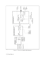
Page 235: ...Figure 11 6 Source Simpli ed Block Diagram Theory of Operation 11 15 ...
Page 244: ...Figure 11 7 Receiver Simpli ed Block Diagram 11 24 Theory of Operation ...
Page 249: ...Figure IDC5S11001 here Figure 11 8 4396B Source Group Block Diagram Theory of Operation 11 29 ...
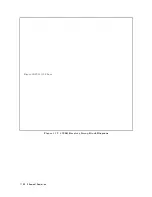
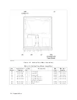
Page 254: ...Figure 12 1 Top View Major Assemblies 12 4 Replaceable Parts ...
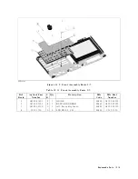
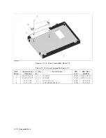
Page 290: ...Figure 12 36 Main Frame Assembly Parts 17 19 12 40 Replaceable Parts ...
Page 294: ......
Page 308: ......
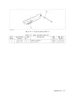
Page 311: ...Figure C 1 Power Cable Supplied Power Requirement C 3 ...
Page 312: ......
Page 324: ......


