


d
a
Backup
Options
Format
Disk
:
ON
(or
OFF)
Verify
Data
:
ON
(or
OFF)
NNNNNNNNNNNNNNNNNNNNNNNNNNNNNNNNNNNNNNNNN
VERIFY
OPTION
toggles
verify
option
on
and
o.
When
the
verify
option
is
set
to
on,
the
system
stored
in
the
exible
diskette
is
veried
to
be
the
same
as
the
current
rmware
in
the
analyzer
after
storing
the
rmware
.
When
the
verify
option
is
set
to
o,
the
verication
is
not
performed.
The
default
setting
is
on.
The
verify
option
setting
is
displayed
as
shown
above
.
NNNNNNNNNNNNNNNNNNNNNNNNNN
CONTINUE
continues
making
the
system
backup
.
Before
pressing
this
softkey
,
insert
a
diskette
into
the
FDD
on
the
front
panel.
NNNNNNNNNNNNNNNNNNNN
CANCEL
stops
making
the
system
backup
and
return
to
the
Bootloader
menu.
W
WWWWWWWWWWWWWWWWWWWWWWWWWWWWWWWWWWWWWWWWWWWWWWWWW
PREVIEW
DISK
Displays
the
revision
information
of
the
rmware
stored
in
the
rmware
diskette
as
shown
below
.
Before
pressing
this
softkey
,
insert
a
rmware
diskette
into
the
FDD
on
the
front
panel.
d
a
Update
Disk
Revision
4396B
Format
Disk
REVN.NN
:
MON
DD
YEAR
where
N.NN:
Revision
Number
MON
DD
YEAR:
Implementation
Date
(Month
Day
Y
ear)
WWWWWWWWWWWWWWWWWWWWWWWWWW
REBOOT
Reboots
the
analyzer
.
If
the
new
rmware
is
installed,
the
analyzer
boots
up
using
the
new
rmware
.
After
pressing
the
softkey
,
the
analyzer
performs
the
normal
power
on
sequence
.
10-46
Service
K
ey
Menus
Summary of Contents for Agilent 4396B
Page 10: ......
Page 32: ......
Page 43: ...Figure 2 7 CAL OUT Level Adjustment Location Adjustments and Correction Constants 2 11 ...
Page 46: ...Figure 2 10 Comb Generator Output 2 14 Adjustments and Correction Constants ...
Page 62: ...Figure 2 26 Final Gain Adjustment Location 2 30 Adjustments and Correction Constants ...
Page 76: ...Figure 3 1 Troubleshooting Organization 3 2 T roubleshooting ...
Page 84: ......
Page 90: ...Figure 5 1 Power Supply Lines Simpli ed Block Diagram 5 2 Power Supply T roubleshooting ...
Page 107: ...Figure 5 12 Power Supply Block Diagram 1 Power Supply T roubleshooting 5 19 ...
Page 108: ...Figure 5 13 Power Supply Block Diagram 2 5 20 Power Supply T roubleshooting ...
Page 109: ...Figure 5 14 Power Supply Block Diagram 3 Power Supply T roubleshooting 5 21 ...
Page 110: ......
Page 112: ...Figure 6 1 Digital Control Group Simpli ed Block Diagram 6 2 Digital Control T roubleshooting ...
Page 124: ......
Page 126: ...Figure 7 1 Source Group Block Diagram 7 2 Source Group T roubleshooting ...
Page 160: ...Figure 8 1 Receiver Group Simpli ed Block Diagram 8 2 Receiver Group T roubleshooting ...
Page 168: ......
Page 184: ...Figure 10 6 External Test Setup 1 Figure 10 7 External Test Setup 2 10 10 Service Key Menus ...
Page 185: ...Figure 10 8 External Test Setup 3 Figure 10 9 External Test Setup 4 Service Key Menus 10 11 ...
Page 226: ...Figure 11 3 Power Supply Functional Group Simpli ed Block Diagram 11 6 Theory of Operation ...
Page 231: ...Figure 11 5 Digital Control Group Simpli ed Block Diagram Theory of Operation 11 11 ...
Page 235: ...Figure 11 6 Source Simpli ed Block Diagram Theory of Operation 11 15 ...
Page 244: ...Figure 11 7 Receiver Simpli ed Block Diagram 11 24 Theory of Operation ...
Page 249: ...Figure IDC5S11001 here Figure 11 8 4396B Source Group Block Diagram Theory of Operation 11 29 ...
Page 254: ...Figure 12 1 Top View Major Assemblies 12 4 Replaceable Parts ...
Page 290: ...Figure 12 36 Main Frame Assembly Parts 17 19 12 40 Replaceable Parts ...
Page 294: ......
Page 308: ......
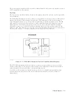
Page 311: ...Figure C 1 Power Cable Supplied Power Requirement C 3 ...
Page 312: ......
Page 324: ......


