


61
converter
automatically
according
to
the
measurement
setting.
NNNNNNNNNNN
POS
selects
the
+1
converter
.
NNNNNNNNNNN
NEG
selects
the
01
converter
.
NNNNNNNNNNNNNNNNNNNNNNNNNNNNNNNNNNNNNNNNNNNNNNNNNNNNN
STEP
DAC
AUTO
man
(:DIAG:SERV:SYNT:STEP:DAC:MODE
{AUTO|MAN}
)
T
oggles
the
STEP
D
A
C
mode
in
the
STEP
LO
to
automatic
mode
or
manual
mode
.
In
the
automatic
mode
,
the
analyzer
sets
the
STEP
D
A
C
control
value
according
to
the
measurement
settings
.
In
the
manual
mode
,
the
STEP
D
A
C
control
value
is
set
by
using
the
NNNNNNNNNNNNNNNNNNNNNNNNNNNNN
DAC
VALUE
softkey
.
NNNNNNNNNNNNNNNNNNNNNNNNNNNNN
DAC
VALUE
(:DIAG:SERV:SYNT:STEP:DAC:VAL
<numeric>)
Allows
you
to
enter
the
STEP
D
A
C
control
value
(0
to
4095).
This
value
is
used
when
the
STEP
D
A
C
is
set
to
manual
mode
.
WWWWWWWWWWWWWWWWWWWWWWWWWWWWWWWWWWWWWWWWWWWWWWWWWWWWWWWWWWWWWWWWW
FREQUENCY
OFFSET
(:DIAG:SERV:SYNT:FREQ:OFFS
<numeric
>)
Allows
you
to
enter
the
frequency
oset
value
.
F
actory
use
only
.
Note
All
settings
must
be
turned
to
auto
except
when
checking
the
analog
circuits
.
10-42
Service
K
ey
Menus
Summary of Contents for Agilent 4396B
Page 10: ......
Page 32: ......
Page 43: ...Figure 2 7 CAL OUT Level Adjustment Location Adjustments and Correction Constants 2 11 ...
Page 46: ...Figure 2 10 Comb Generator Output 2 14 Adjustments and Correction Constants ...
Page 62: ...Figure 2 26 Final Gain Adjustment Location 2 30 Adjustments and Correction Constants ...
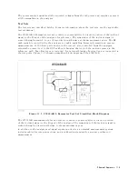
Page 76: ...Figure 3 1 Troubleshooting Organization 3 2 T roubleshooting ...
Page 84: ......
Page 90: ...Figure 5 1 Power Supply Lines Simpli ed Block Diagram 5 2 Power Supply T roubleshooting ...
Page 107: ...Figure 5 12 Power Supply Block Diagram 1 Power Supply T roubleshooting 5 19 ...
Page 108: ...Figure 5 13 Power Supply Block Diagram 2 5 20 Power Supply T roubleshooting ...
Page 109: ...Figure 5 14 Power Supply Block Diagram 3 Power Supply T roubleshooting 5 21 ...
Page 110: ......
Page 112: ...Figure 6 1 Digital Control Group Simpli ed Block Diagram 6 2 Digital Control T roubleshooting ...
Page 124: ......
Page 126: ...Figure 7 1 Source Group Block Diagram 7 2 Source Group T roubleshooting ...
Page 160: ...Figure 8 1 Receiver Group Simpli ed Block Diagram 8 2 Receiver Group T roubleshooting ...
Page 168: ......
Page 184: ...Figure 10 6 External Test Setup 1 Figure 10 7 External Test Setup 2 10 10 Service Key Menus ...
Page 185: ...Figure 10 8 External Test Setup 3 Figure 10 9 External Test Setup 4 Service Key Menus 10 11 ...
Page 226: ...Figure 11 3 Power Supply Functional Group Simpli ed Block Diagram 11 6 Theory of Operation ...
Page 231: ...Figure 11 5 Digital Control Group Simpli ed Block Diagram Theory of Operation 11 11 ...
Page 235: ...Figure 11 6 Source Simpli ed Block Diagram Theory of Operation 11 15 ...
Page 244: ...Figure 11 7 Receiver Simpli ed Block Diagram 11 24 Theory of Operation ...
Page 249: ...Figure IDC5S11001 here Figure 11 8 4396B Source Group Block Diagram Theory of Operation 11 29 ...
Page 254: ...Figure 12 1 Top View Major Assemblies 12 4 Replaceable Parts ...
Page 290: ...Figure 12 36 Main Frame Assembly Parts 17 19 12 40 Replaceable Parts ...
Page 294: ......
Page 308: ......
Page 311: ...Figure C 1 Power Cable Supplied Power Requirement C 3 ...
Page 312: ......
Page 324: ......


