


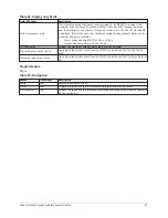


Table 80: Display only fields
Field/LED name
Description
Motor 1 and 2: Motor current limit
setpoint
Displays the current limit being applied to compressor #1 motor. If both compressor
motors are running, it displays the active Chiller Current Limit value.
If only compressor motor #1 is running:
•
If the Lead Compressor Pulldown Time Setpoint is in effect, it is the Lead
Compressor Pulldown Demand Limit Setpoint value.
•
If the Lead Compressor Pulldown Time Setpoint is not in effect, it is twice the
Chiller Current Limit, up to 100%.
Motor 1 and 2: Operating hours
Displays the total accumulated run time of compressor #1.
Motor 1 and 2: Number of starts
Displays the total accumulated number of starts of compressor #1.
Motor 1 and 2: Run time
Displays the amount of time in days, hours and minutes that compressor #1 motor
has been running since the last start signal was received. Value is reset to zero when
compressor #1 enters Coastdown. It remains at zero while shutdown.
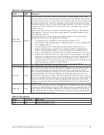
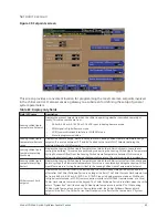
Table 81: Programmable
Button
Access level
Description
Local chiller
current limit
Operator
Allows the user to specify the maximum allowed Chiller Current. The Chiller Current is
the total motor current being conducted by the chiller. If only one compressor motor
is running, that is the Chiller Current. If both compressor motors are running, the
Chiller Current is the total of both motors, with the Pre-rotation Vanes operated to
achieve equal current to both motors. The Chiller Full Load Amps (FLA) is the total of
compressor #1 motor and compressor #2 motor FLA ratings, with each motor having
an equal FLA rating.
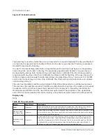
For example, if the Chiller FLA is 1600 A, the FLA of each motor is 800 A. The Chiller
Current Limit Setpoint is expressed as a percentage (30% to 100%) of Chiller FLA. In
this example, the chiller FLA is 1600 A. If the Chiller Current Limit Setpoint is set at 70%,
the Chiller Current is limited to 1120 A. If only one motor is running, the Motor Current
Limit (see Motor Current Limit Setpoint above) for that motor would be set to 100%
and it would be allowed to operate at its maximum of 800 A, However, if both motors
are running, each would be limited to 560 A per motor, producing a Chiller Current of
1120 A.
This setpoint is in effect after the Lead Compressor Pulldown Time setpoint has
elapsed and for the remainder of system run.
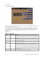
Lead compressor
pulldown
demand limit
Operator
Allows the user to specify a motor current limit (30% to 100% FLA) that’s applied
to the Lead compressor motor during the time period programmed as the LEAD
COMPRESSOR PULLDOWN TIME Setpoint. This current limit applies to the Full Load
Amps of the Lead compressor motor only, not the Chiller Full Load Amps (total of
both compressors). For example, if the Chiller Full Load Amps is 2000 A, then each
compressor’s FLA is 1000 A. If set to 80%, then the lead compressor motor current
would be limited to 800 A (80% x 1000) for the duration of this period.
Lead compressor
pulldown time
Operator
This setpoint is used to limit the chiller to single compressor operation for a specified
duration (0-255 minutes) when starting the chiller. While this pulldown time is in
effect,
System in Lead Compressor Pulldown
is displayed on the system details
line along with the time remaining in the period. During this time, only the lead
compressor is permitted to run. The lag compressor will not be brought on line.
After this time has elapsed, the lag compressor can be brought on line per normal
operation. While this period is in effect, the lead compressor motor current will be
limited to the value programmed for the
Lead Compressor Pulldown Demand
Limit
setpoint (30-100% FLA).
After the
Lead Compressor Pulldown Time
setpoint has elapsed, the chiller current
limit will be limited to the value programmed for the
Current Limit
setpoint.
91
Model YD Mod D with OptiView Control Center
Содержание YD Mod D
Страница 2: ...2 Model YD Mod D with OptiView Control Center...
Страница 8: ...Nomenclature Model YD Mod D with OptiView Control Center 8...
Страница 17: ...Figure 2 Chiller operation flow chart 17 Model YD Mod D with OptiView Control Center...
Страница 18: ...Figure 2 Chiller operation flow chart Model YD Mod D with OptiView Control Center 18...
Страница 19: ...Figure 2 Chiller operation flow chart 19 Model YD Mod D with OptiView Control Center...
Страница 20: ...Figure 2 Chiller operation flow chart Model YD Mod D with OptiView Control Center 20...
Страница 21: ...Figure 2 Chiller operation flow chart 21 Model YD Mod D with OptiView Control Center...
Страница 22: ...Figure 2 Chiller operation flow chart Model YD Mod D with OptiView Control Center 22...
Страница 150: ...Figure 57 Sample printout status Model YD Mod D with OptiView Control Center 150...
Страница 151: ...Figure 57 Sample printout status 151 Model YD Mod D with OptiView Control Center...
Страница 152: ...Figure 58 Sample printout setpoints Model YD Mod D with OptiView Control Center 152...
Страница 153: ...Figure 58 Sample printout setpoints 153 Model YD Mod D with OptiView Control Center...
Страница 154: ...Figure 59 Sample printout schedule Model YD Mod D with OptiView Control Center 154...
Страница 155: ...Figure 60 Sample printout sales order 155 Model YD Mod D with OptiView Control Center...
Страница 156: ...Figure 61 Sample printout history Model YD Mod D with OptiView Control Center 156...
Страница 157: ...Figure 61 Sample printout history 157 Model YD Mod D with OptiView Control Center...
Страница 159: ...Figure 64 Sample printout custom screen report 159 Model YD Mod D with OptiView Control Center...