


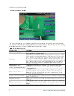
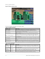


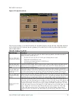

Low voltage variable speed drive screen
Figure 28: Low voltage variable speed drive screen
This screen displays information about the Low Voltage Variable Speed Drive (VSD), if installed.
There are two similar screens available: one for VSD 1 and another for VSD 2.
Table 67: Display only fields
Field/LED name
Description
Motor run (LED)
Indicates whether the digital output from the controls is commanding the motor to
RUN.
Motor heater (LED)
Indicates whether the digital output from the controls is commanding the optional
motor heater on. This LED is not displayed if the option is not installed.
% Full Load Amps
Displays the motor current as a percentage of the Full Load Amps (FLA) value.
Motor current limit setpoint
Displays the current limit value in use. This value could come from a 0 mA to 20 mA, 4
mA to 20 mA, 0 VDC to 10 VDC, or 2 VDC to 10 VDC input in Analog Remote mode, PWM
signal in Digital Remote mode, SC-EQ communications interface in ISN (BAS) mode, or
a locally programmed value.
PRV position
Displays the Pre-rotation Vane position as a value between 0% and 100%.
Pulldown demand time left
Displays the time remaining in the programmed pulldown period if the value is
nonzero.
Output voltage
Displays the output voltage measured to the motor.
Output frequency
Displays the present output frequency to the motor.
Input power
Displays the total kilowatts measured by the VSD or Harmonic Filter, if installed.
KW hours
Displays the cumulative amount of kilowatts used over time as the VSD motor
controller operates.
Output current - phase A, B, C
Displays the phase current measured to the motor.
Voltage total harmonic distortion -
(L1, L2, L3)
Displays the Total Harmonic Distortion (THD) for each of the voltage lines as calculated
by the optional filter.
Supply current total demand
distortion - (L1, L2, L3)
Displays the Total Dynamic Distortion (TDD) for each of the supply current lines as
calculated by the optional filter.
Supply kVa
Displays the supply kVa measured by the optional filter.
Total power factor
Displays the relationship between the Input Power and the Supply kVA when the
optional filter is installed.
Model YD Mod D with OptiView Control Center
78
Содержание YD Mod D
Страница 2: ...2 Model YD Mod D with OptiView Control Center...
Страница 8: ...Nomenclature Model YD Mod D with OptiView Control Center 8...
Страница 17: ...Figure 2 Chiller operation flow chart 17 Model YD Mod D with OptiView Control Center...
Страница 18: ...Figure 2 Chiller operation flow chart Model YD Mod D with OptiView Control Center 18...
Страница 19: ...Figure 2 Chiller operation flow chart 19 Model YD Mod D with OptiView Control Center...
Страница 20: ...Figure 2 Chiller operation flow chart Model YD Mod D with OptiView Control Center 20...
Страница 21: ...Figure 2 Chiller operation flow chart 21 Model YD Mod D with OptiView Control Center...
Страница 22: ...Figure 2 Chiller operation flow chart Model YD Mod D with OptiView Control Center 22...
Страница 150: ...Figure 57 Sample printout status Model YD Mod D with OptiView Control Center 150...
Страница 151: ...Figure 57 Sample printout status 151 Model YD Mod D with OptiView Control Center...
Страница 152: ...Figure 58 Sample printout setpoints Model YD Mod D with OptiView Control Center 152...
Страница 153: ...Figure 58 Sample printout setpoints 153 Model YD Mod D with OptiView Control Center...
Страница 154: ...Figure 59 Sample printout schedule Model YD Mod D with OptiView Control Center 154...
Страница 155: ...Figure 60 Sample printout sales order 155 Model YD Mod D with OptiView Control Center...
Страница 156: ...Figure 61 Sample printout history Model YD Mod D with OptiView Control Center 156...
Страница 157: ...Figure 61 Sample printout history 157 Model YD Mod D with OptiView Control Center...
Страница 159: ...Figure 64 Sample printout custom screen report 159 Model YD Mod D with OptiView Control Center...