


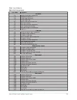
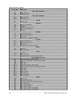
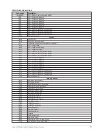


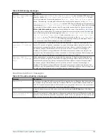


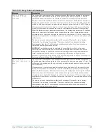


Table 140: Warning messages
Message
Description
Warning – Head Pressure
– High Head Lag Start
Limit
Displayed when starting the lag compressor while a high head condition exists. A high head
condition exists when the actual
Delta P/P
is greater than the
High Head DP/P Limit
setpoint. To minimize surging while starting the lag compressor under this condition, the
lead compressor’s pre-rotation vanes are driven closed coincident with the start of the lag
compressor’s pre-lube. They will be allowed to open after the lag compressor is running, the
lag discharge valve is open and the lead and lag motor currents are balanced within 5%.
Warning – Anti Surge –
Excess Surge Limit
This warning applies to dual compressor operation only. The pre-rotation vanes are being
load limited because a surge event has been detected while both compressors are running.
As a surge avoidance, a close signal is applied to both the lead and lag compressor vanes
until the lowest motor current is greater than or equal to 80% of the highest motor current.
The load limit will remain in effect until the lag compressor is shutdown, whereupon the
message is cleared.
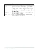
Warning – Anti Surge –
Surge Count Exceeded
This warning applies to dual compressor operation only. The
Surge Window Count
exceeded the
Count Limit
while both compressors were running. To prevent further
surging, a soft shutdown is performed on the lag compressor when this warning is
displayed. This message will be displayed until manually cleared with the
Warning Reset
key
in operator (or higher) access level.
Warning – Compressor #1
Locked Out
Compressor 1 is inhibited from starting because it has been placed in service lockout. This is
performed on the Compressor capacity cycling screen.
Warning – Compressor #2
Locked Out
Compressor 2 is inhibited from starting because it has been placed in service lockout. This is
performed on the Compressor capacity cycling screen.
Warning – Oil Pump #1 –
Seal Lubrication - Low
Pressure
A minimum of 15 psid of oil pressure was not achieved in the first 30 seconds of the seal
lubrication cycle (or it dropped below this value during the remaining 90 seconds of the
cycle) for compressor 1. This message must be manually cleared using the
Warning Reset
key in Service access level (or higher). As soon as the message is cleared, another seal
lubrication will be attempted. The message will also be cleared if Standby Lube 1 is disabled
on Oil pump 1 screen or compressor 1 enters the prelube state.
Warning – Oil Pump #2 –
Seal Lubrication - Low
Pressure
A minimum of 15 psid of oil pressure was not achieved in the first 30 seconds of the seal
lubrication cycle (or it dropped below this value during the remaining 90 seconds of the
cycle) for compressor 2. This message must be manually cleared using the
Warning Reset
key in service access level (or higher). As soon as the message is cleared, another seal
lubrication will be attempted. The message will also be cleared if standby lube 2 is disabled
on Oil pump 2 screen or compressor 1 enters the prelube state.
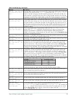
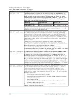
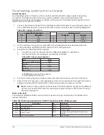
Warning – Low Oil Level
Displayed if the oil level in the oil sump is less than the minimum oil level as shown below.
Condition
Minimum oil level
No compressors running
50%
1 compressor running
40%
2 compressors running
30%
It will automatically clear when the level is greater than the minimum oil level.
Warning – Oil Pump #1
– Seal Lubrication In
Progress
The 2 minute seal lubrication cycle (that occurs once every 24 hours while the compressor 1
is not running) is in progress for compressor 1.
Warning – Oil Pump #2
– Seal Lubrication In
Progress
The 2 minute seal lubrication cycle (that occurs once every 24 hours while compressor 2 is
not running) is in progress for compressor 2.
Warning – Vanes #1 –
Uncalibrated
The pre-rotation vanes calibration procedure has not been performed on compressor 1.
Warning – Vanes #2 –
Uncalibrated
The pre-rotation vanes calibration procedure has not been performed on compressor 2
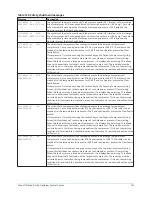
Warning – Surge
Protection - Excess
Surge Detected
This warning applies only to single compressor operation and only if the
Surge
Protection Shutdown
setpoint is disabled. The
Surge Window Count
has exceeded the
Count Limit
setpoint during single compressor operation. This message can be cleared
with the
Warning Reset
key in operator access level (or higher) after the
Surge Window
Count
is less than the
Count Limit
.
133
Model YD Mod D with OptiView Control Center
Содержание YD Mod D
Страница 2: ...2 Model YD Mod D with OptiView Control Center...
Страница 8: ...Nomenclature Model YD Mod D with OptiView Control Center 8...
Страница 17: ...Figure 2 Chiller operation flow chart 17 Model YD Mod D with OptiView Control Center...
Страница 18: ...Figure 2 Chiller operation flow chart Model YD Mod D with OptiView Control Center 18...
Страница 19: ...Figure 2 Chiller operation flow chart 19 Model YD Mod D with OptiView Control Center...
Страница 20: ...Figure 2 Chiller operation flow chart Model YD Mod D with OptiView Control Center 20...
Страница 21: ...Figure 2 Chiller operation flow chart 21 Model YD Mod D with OptiView Control Center...
Страница 22: ...Figure 2 Chiller operation flow chart Model YD Mod D with OptiView Control Center 22...
Страница 150: ...Figure 57 Sample printout status Model YD Mod D with OptiView Control Center 150...
Страница 151: ...Figure 57 Sample printout status 151 Model YD Mod D with OptiView Control Center...
Страница 152: ...Figure 58 Sample printout setpoints Model YD Mod D with OptiView Control Center 152...
Страница 153: ...Figure 58 Sample printout setpoints 153 Model YD Mod D with OptiView Control Center...
Страница 154: ...Figure 59 Sample printout schedule Model YD Mod D with OptiView Control Center 154...
Страница 155: ...Figure 60 Sample printout sales order 155 Model YD Mod D with OptiView Control Center...
Страница 156: ...Figure 61 Sample printout history Model YD Mod D with OptiView Control Center 156...
Страница 157: ...Figure 61 Sample printout history 157 Model YD Mod D with OptiView Control Center...
Страница 159: ...Figure 64 Sample printout custom screen report 159 Model YD Mod D with OptiView Control Center...