


has opened, the Condenser Refrigerant Control ramp-up period begins as described in
refrigerant level control – lag start
. While both compressors are running, the variable geometry
diffusers are modulated according to the stall activity and pre-rotation vanes position. There is no
VGD response to surge activity.
When both compressors have been brought online, run for at least 30 minutes, unless the anti-
recycle feature has been disabled, a fault is detected, or a Local or Remote stop is applied. After the
30 minute waiting period, a soft shutdown, as described in
the lag compressor if the lead compressor motor current goes below the
Low Load setpoint
(20%
to 60%; default 45%) for a period equal to the
Low Load Time setpoint
(1 to 20 minutes; default 5).
Lag compressor start with high head
When operating at high head conditions, surges can occur while going from one compressor to two
compressor operation. A high-head condition is detected by measuring the Delta P/P [
(Condenser
pressure – Evaporator pressure) / Evaporator pressure
] and comparing it to the
High Head DP/P Limit setpoint. By closing the lead compressor’s pre-rotation vanes during a lag
compressor start when a high head condition is present, surge conditions can be minimized.
With the lead compressor running and it is determined the lag compressor is required to run, the
Delta P/P is measured. If it is > the High Head DP/P Limit setpoint, a close signal is applied to the
lead compressor’s pre-rotation vanes coincident with the start of the lag compressor’s pre-lube.
They can open when all the following conditions are met:
•
The lag compressor is running
•
The lag discharge valve is open
•
The difference between the lead and lag motor currents is < 5%
An LED on the Surge – Dual Compressor Setup screen and the Capacity Compressor Cycling
screen illuminates whenever a high head Lag compressor start condition exists. Also, the message
Warning – Head Pressure – High Head Lag Start Limit
appears on the System Status line
of the display during this condition.
Condenser refrigerant level control – lag start
When operating at low condenser liquid temperatures, a Low Evaporator Pressure trip can occur
when going from one compressor to two compressor operation.
During startup of the lag compressor, as the lag discharge valve opens, the system will see a step
change in refrigerant flow. Although the Condenser Refrigerant Level Control keeps the refrigerant
level stable during normal operation, the variable orifice does not open quickly enough when the
lag compressor is started. This causes the refrigerant to stack in the in the condenser, starving the
evaporator, and causing a low evaporator pressure shutdown.
The condenser Refrigerant Level Control Lag Start mode is initiated when the lag compressor
enters prelube and is terminated 2 minutes after the lag discharge valve has opened. During this
mode, if the refrigerant level is > 20%, the level control lower (valve open) output is turned on for 5
seconds every 10 seconds until the level is less than 20%. If the refrigerant level is < 20%, the level
control is held in place.
After the Lag Start mode has ended, a linearly increasing ramp limit, called the Refrigerant Level
Target, is applied to the Refrigerant Level setpoint. This ramp allows the level to go from the
present level (20%) to the programmed Refrigerant Level setpoint over a period equal to one-half of
the Valve Preset Time setpoint. During this ramp-up period, the Refrigerant Level target is used to
control the refrigerant level in the condenser. The Refrigerant Level setpoint is then used to control
the level for the remainder of the run period.
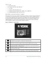
On the Refrigerant Level Control screen, the Refrigerant Level Override Mode displays
Valve
Preset
during the pre-positioning of the refrigerant level control valve while bringing on the lead
compressor. It displays
Lag Start
when performing the Refrigerant Level Control Lag Start mode
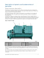
Model YD Mod D with OptiView Control Center
12
Содержание YD Mod D
Страница 2: ...2 Model YD Mod D with OptiView Control Center...
Страница 8: ...Nomenclature Model YD Mod D with OptiView Control Center 8...
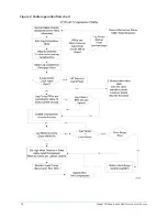
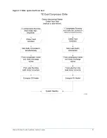
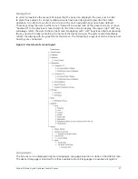
Страница 17: ...Figure 2 Chiller operation flow chart 17 Model YD Mod D with OptiView Control Center...
Страница 18: ...Figure 2 Chiller operation flow chart Model YD Mod D with OptiView Control Center 18...
Страница 19: ...Figure 2 Chiller operation flow chart 19 Model YD Mod D with OptiView Control Center...
Страница 20: ...Figure 2 Chiller operation flow chart Model YD Mod D with OptiView Control Center 20...
Страница 21: ...Figure 2 Chiller operation flow chart 21 Model YD Mod D with OptiView Control Center...
Страница 22: ...Figure 2 Chiller operation flow chart Model YD Mod D with OptiView Control Center 22...
Страница 150: ...Figure 57 Sample printout status Model YD Mod D with OptiView Control Center 150...
Страница 151: ...Figure 57 Sample printout status 151 Model YD Mod D with OptiView Control Center...
Страница 152: ...Figure 58 Sample printout setpoints Model YD Mod D with OptiView Control Center 152...
Страница 153: ...Figure 58 Sample printout setpoints 153 Model YD Mod D with OptiView Control Center...
Страница 154: ...Figure 59 Sample printout schedule Model YD Mod D with OptiView Control Center 154...
Страница 155: ...Figure 60 Sample printout sales order 155 Model YD Mod D with OptiView Control Center...
Страница 156: ...Figure 61 Sample printout history Model YD Mod D with OptiView Control Center 156...
Страница 157: ...Figure 61 Sample printout history 157 Model YD Mod D with OptiView Control Center...
Страница 159: ...Figure 64 Sample printout custom screen report 159 Model YD Mod D with OptiView Control Center...