


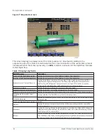


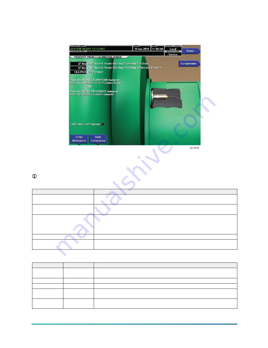
Proximity probe calibration screen
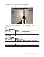
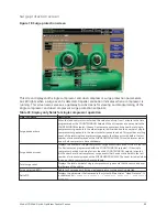
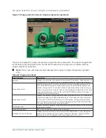
Figure 12: Proximity probe calibration screen
This screen displays a cutaway view of the chiller compressor, revealing the proximity probe sensor
and provides the capability of calibrating the proximity probe sensor. The appearance of this screen
is the same for compressor #1 and compressor #2.
Note:
Requires a login access level of SERVICE.
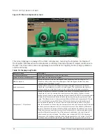
Table 21: Display only fields
Field/LED name
Description
High speed thrust bearing proximity
position
Displays the distance between the high-speed thrust collar and the proximity probe
that is used to measure the position.
High speed thrust bearing proximity
reference position
Displays the presently defined offset reference position. This value is defined at the
conclusion of a calibration sequence.
Oil pressure
Displays the pressure differential between the pump oil pressure transducer
(compressor bearing input) and the sump oil pressure transducer. If either of the
transducers used to calculate this differential is out of range, the display field will show
XX.X.
Calibration in progress (LED)
Indicates that the calibration sequence is in progress.
Calibration messages
These are text messages which step the user through the calibration process and
indicate its success or failure.
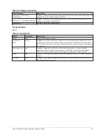
Table 22: Programmable
Button
Access level
Description
Enter reference
Service
Allows the Service Technician to enter a previously recorded reference when replacing
a microboard.
Start calibration Service
This starts the calibration procedure. This key is hidden after calibration has started.
Cancel calibration Service
This option only becomes available after the calibration has started.
Accept calibration Service
The key is pressed to accept the calibration. This key option only becomes available
after the calibration sequence is complete.
Fault
acknowledge
Service
This option is only displayed if a fault is present. Allows clearing of High Speed Thrust
Bearing related shutdowns.
Model YD Mod D with OptiView Control Center
44
Содержание YD Mod D
Страница 2: ...2 Model YD Mod D with OptiView Control Center...
Страница 8: ...Nomenclature Model YD Mod D with OptiView Control Center 8...
Страница 17: ...Figure 2 Chiller operation flow chart 17 Model YD Mod D with OptiView Control Center...
Страница 18: ...Figure 2 Chiller operation flow chart Model YD Mod D with OptiView Control Center 18...
Страница 19: ...Figure 2 Chiller operation flow chart 19 Model YD Mod D with OptiView Control Center...
Страница 20: ...Figure 2 Chiller operation flow chart Model YD Mod D with OptiView Control Center 20...
Страница 21: ...Figure 2 Chiller operation flow chart 21 Model YD Mod D with OptiView Control Center...
Страница 22: ...Figure 2 Chiller operation flow chart Model YD Mod D with OptiView Control Center 22...
Страница 150: ...Figure 57 Sample printout status Model YD Mod D with OptiView Control Center 150...
Страница 151: ...Figure 57 Sample printout status 151 Model YD Mod D with OptiView Control Center...
Страница 152: ...Figure 58 Sample printout setpoints Model YD Mod D with OptiView Control Center 152...
Страница 153: ...Figure 58 Sample printout setpoints 153 Model YD Mod D with OptiView Control Center...
Страница 154: ...Figure 59 Sample printout schedule Model YD Mod D with OptiView Control Center 154...
Страница 155: ...Figure 60 Sample printout sales order 155 Model YD Mod D with OptiView Control Center...
Страница 156: ...Figure 61 Sample printout history Model YD Mod D with OptiView Control Center 156...
Страница 157: ...Figure 61 Sample printout history 157 Model YD Mod D with OptiView Control Center...
Страница 159: ...Figure 64 Sample printout custom screen report 159 Model YD Mod D with OptiView Control Center...