


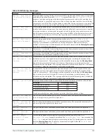

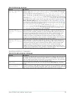


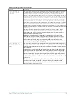


Table 140: Warning messages
Message
Description
Warning – Motor Bearing
Lube Required
The
Operating Hours Since Last Motor Lubrication
has exceeded 1200 hours (the
greater of either
Motor #1 Operating Hours
or
Motor #2 Operating Hours
is used
for this calculation). This warning replaces
Warning – Motor Bearing Lube Suggested
above. This warning is displayed until manually cleared by the operator or the
Operating
Hours Since Last Motor Lubrication
exceed 1400 hours, whereupon it is replaced by
the message
Motor – Lack of Bearing Lubrication
. The operator clears this message
by entering his/her initials, name or user ID in operator access level (or higher) using the
Motor Lube Acknowledge
key on the Motor lubrication screen. See the
for entry instructions. This entry implies both motors were lubricated. The date and
time of this entry is automatically logged as the
Date of Last Motor Lubrication
and
Time of Last Motor Lubrication
. It also resets the
Operating Hours Since Last
Lubrication
to zero. The date this warning occurs is stored as the
Date of Last Motor
Lubrication Warning or Fault
. This warning message will only be displayed if the
Auto
lube
setpoint on the Motor lubrication screen is disabled.
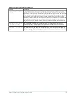
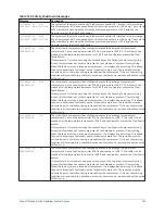
Possible Leak In
Compressor 1 Discharge
Valve
When compressor 2 is running in the lead and compressor 1 (lag) is either stopped or in
the last 10 seconds of system coastdown, an open discharge valve is detected on the lag
compressor by comparing the lag compressor stall transducer output to the evaporator
transducer output. If the difference is >16 psid for at least 1 second, this message is
displayed. This check is only performed if the lead compressor has been running for 5 or
more seconds, the evaporator pressure transducer is sensing a pressure that is in range (6 –
74 psig) and the stall transducer is installed and its output is > 0.5 VDC.
Possible Leak In
Compressor 2 Discharge
Valve
When compressor 1 is running in the lead and compressor 2 (lag) is either stopped or in
the last 10 seconds of system coastdown, an open discharge valve is detected on the lag
compressor by comparing the lag compressor stall transducer output to the evaporator
transducer output. If the difference is >16 psid for at least 1 second, this message is
displayed. This check is only performed if the lead compressor has been running for 5 or
more seconds, the evaporator pressure transducer is sensing a pressure that is in range (6 –
74 psig) and the stall transducer is installed and its output is > 0.5 VDC.
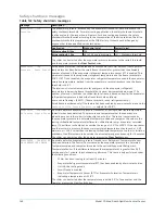
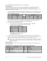
Routine shutdown messages
Table 141: Routine shutdown messages
Message
Description
Remote Stop
A shutdown command has been received from a remote device. Remote stop commands can
be received in digital remote mode via I/O Board TB4-7/8 or in ISN (BAS) remote mode via
the SC-EQ serial communications. If the chiller is running when this occurs, the pre-rotation
vanes are driven fully closed prior to shutting down the chiller.
Local Stop
A local shutdown command has been received by placing the
Soft Stop
key on the Home
screen.
Place Compressor Switch
In Run Position
The control center is in either digital or integrated systems network (ISN) remote mode. The
operator is requested to place the compressor switch in the run position. The control center
will not accept a remote start/stop command unless the switch is in the run position.
135
Model YD Mod D with OptiView Control Center
Содержание YD Mod D
Страница 2: ...2 Model YD Mod D with OptiView Control Center...
Страница 8: ...Nomenclature Model YD Mod D with OptiView Control Center 8...
Страница 17: ...Figure 2 Chiller operation flow chart 17 Model YD Mod D with OptiView Control Center...
Страница 18: ...Figure 2 Chiller operation flow chart Model YD Mod D with OptiView Control Center 18...
Страница 19: ...Figure 2 Chiller operation flow chart 19 Model YD Mod D with OptiView Control Center...
Страница 20: ...Figure 2 Chiller operation flow chart Model YD Mod D with OptiView Control Center 20...
Страница 21: ...Figure 2 Chiller operation flow chart 21 Model YD Mod D with OptiView Control Center...
Страница 22: ...Figure 2 Chiller operation flow chart Model YD Mod D with OptiView Control Center 22...
Страница 150: ...Figure 57 Sample printout status Model YD Mod D with OptiView Control Center 150...
Страница 151: ...Figure 57 Sample printout status 151 Model YD Mod D with OptiView Control Center...
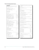
Страница 152: ...Figure 58 Sample printout setpoints Model YD Mod D with OptiView Control Center 152...
Страница 153: ...Figure 58 Sample printout setpoints 153 Model YD Mod D with OptiView Control Center...
Страница 154: ...Figure 59 Sample printout schedule Model YD Mod D with OptiView Control Center 154...
Страница 155: ...Figure 60 Sample printout sales order 155 Model YD Mod D with OptiView Control Center...
Страница 156: ...Figure 61 Sample printout history Model YD Mod D with OptiView Control Center 156...
Страница 157: ...Figure 61 Sample printout history 157 Model YD Mod D with OptiView Control Center...
Страница 159: ...Figure 64 Sample printout custom screen report 159 Model YD Mod D with OptiView Control Center...