84
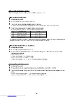
The
fol
lo
w
in
g l
e
a
k
ag
e a
n
d
cl
og
gi
ng
che
ck m
a
y n
o
t w
o
rk
pr
o
per
ly
i
f t
he
ou
tdo
or
te
mp
er
at
ur
e i
s
l
o
w
an
d th
e r
e
fr
ig
er
an
t i
s
hi
be
rn
at
in
g.
In
this ca
se,
set
the
op
eratin
g t
ime
un
til
the
che
ck lon
ge
r.
(A
pp
ro
xi
ma
te gu
id
e: Di
sch
ar
ge
te
mp
er
at
ur
e
TD
1
,
TD
2, and
TD
3 60 °C or
hi
g
h
e
r)
(*1
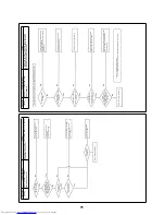
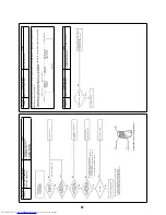
)Check th
e va
lve lea
kage an
d cl
ogg
ing
a)
C
heck the SV3A valve leakage (Performed
only in the outdo
or unit linkage system)
•
T
ur
n
off
the
p
o
wer
, r
e
mo
ve t
h
e
SV3
A va
lve co
nn
ecto
r,
tur
n
on
th
e p
o
wer
a
nd
the
n st
ar
t th
e
test
ru
n.
•
W
h
ile
th
e
o
u
td
oo
r u
n
it
is ru
nn
in
g,
che
ck th
e
t
e
mp
era
tu
re
ch
an
ge
on
th
e S
V
3
A
valve
seco
nd
ar
y.
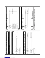
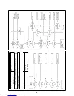
–Fig
ur
e (1
)
ĺ
If
th
e te
m
p
er
a
tur
e
bec
om
es h
igh,
th
e SV
3A
val
ve
l
eaka
ge
ha
s occ
ur
re
d.
Re
pl
a
c
e th
e
SV3
A va
lve
.
b)
C
heck the SV3C
valve leakage
•
u
rn
off
th
e p
o
wer
, r
e
mo
ve t
h
e
SV3
C valve
con
ne
ctor
, t
u
rn
o
n
t
h
e
po
w
e
r an
d th
en
sta
rt
the
te
st r
u
n
.
•
A
ft
er
se
ver
al
-m
in
u
te
op
er
at
io
n,
che
ck th
e te
m
per
a
tur
e
on
the
SV
3C
va
lve
sec
ond
a
ry.–
Fig
u
re
(2
)
ĺ
If
th
e te
m
p
er
a
tur
e
bec
om
es h
igh
(e
qu
iv
al
en
t to
di
sch
ar
ge
tem
p
e
ratu
re
TD
),
th
e S
V
3
C
val
ve l
e
aka
ge
ha
s
occu
rre
d.
Re
pl
ace
t
h
e S
V
3
C va
lve.
(Eve
n if
the
SV
3C va
lv
e
lea
kag
e
h
a
s n
o
t
occu
rr
ed
, th
e
tempe
ratu
re
on
th
e S
V
3C va
lve se
con
da
ry
r
ise
s du
ri
n
g
op
er
at
io
n.
(L
ow
er t
h
an
d
is
c
h
ar
ge
te
mp
er
at
ur
e TD)
)
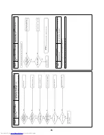
c)
C
heck the SV3F
va
lve le
akage
•
T
u
rn o
ff t
h
e po
we
r,
rem
ov
e
th
e
S
V
3
F v
a
lv
e c
o
nn
ec
to
r,
tu
rn
on
th
e p
o
w
e
r a
n
d
th
e
n
s
tar
t t
h
e t
e
s
t ru
n.
•
A
ft
er
se
ver
al
-m
in
u
te
op
er
at
io
n,
che
ck th
e te
m
per
a
tur
e
on
the
SV
3F va
lve
se
cond
ar
y.–
Fig
u
re
(3
)
ĺ
If
th
e te
m
p
er
a
tur
e
bec
om
es h
igh,
th
e SV
3F va
lve le
akag
e
has
occu
rr
ed
. Re
place
the
SV
3F va
lve.
d)
C
heck the SV3B valve cloggin
g (Perfo
rmed only in th
e outdoor unit linkag
e system)
•
S
e
t [
S
W
0
1
/
SW
02
/
SW
03]
to
[2
/
1
/ 3
]
(7
-se
gm
en
t
display
[Hr
][..
. ..
. .
..])
wh
ile
th
e
out
do
or
u
n
it is
ru
nn
ing,
an
d
the
n
pr
e
ss [SW
0
4] f
o
r 2
seco
nds
or
lon
g
er
.
•
S
e
t [S
W0
2]
to
[10
], a
n
d
tur
n
on
SV
3A,
SV3
B,
and
SV
3C. (
7
-se
gm
en
t d
isp
lay [
H
r]
[... 3
–
])
•
W
h
ile
th
e
o
u
td
oo
r u
n
it
is ru
nn
in
g,
che
ck th
e
t
e
mp
era
tu
re
ch
an
ge
on
th
e S
V
3
B
valve
seco
nd
ar
y.
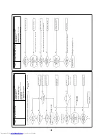
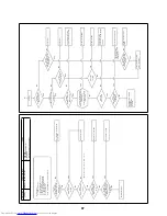
–Fig
ur
e (4
)
ĺ
If
th
e te
m
p
er
a
tur
e
doe
s n
o
t b
e
co
me
h
ig
h
(
e
quiva
lent
to
ou
tdo
or
te
mp
er
at
ur
e)
, th
e
SV3
B va
lve
is clog
ge
d.
Re
place
th
e S
V
3B
valve
.
e)
C
heck the SV3E valve cloggin
g
R
e
set the
po
wer
Ļ
Co
nfi
rm
tha
t th
e S
V
3E
val
ve
is
tur
ne
d o
n
/
off
(so
un
d /
coi
l sur
fa
ce te
mp
er
at
ur
e r
isi
ng
) b
y
th
e "
v
al
ve f
o
rc
ed
op
en
/ cl
ose
fun
ction
" o
f th
e o
u
td
oo
r
un
it
.
Ļ
Sta
rt
the
coo
lin
g
or
he
atin
g te
st r
u
n.
Ļ
Afte
r
seve
ra
l mi
n
u
te
s of
th
e co
mp
re
ssor
o
p
e
ra
ti
o
n
, ch
eck th
e
pi
pe
tem
p
e
ratu
re
o
n
t
he
SV3
E va
lv
e e
x
it
. If
the
te
mp
era
tu
re
d
o
e
s
no
t c
h
an
g
e
or
is
e
q
uiv
a
le
n
t t
o
t
h
e
ou
td
o
o
r
te
mp
era
tu
re
, t
h
e
SV
3E
ma
y
b
e
c
log
ge
d.
–
F
igu
re
(5)
(R
e
fer
en
ce)
If th
e S
V
3
E
va
lv
e
is clog
ge
d,
all the
TK1
, TK2
, TK
3, TK
4 a
n
d
TK5
temp
e
ratu
re
s d
o
n
o
t
chan
ge
an
y more.
f)
C
heck the SV3F
va
lve clogging
•
S
e
t [
S
W
0
1
/
SW
02
/
SW
03]
to
[2
/
1
/ 3
]
(7
-se
gm
en
t
display
[Hr
][..
. ..
. .
..])
wh
ile
th
e
out
do
or
u
n
it is
ru
nn
ing,
an
d
the
n
pr
e
ss [SW
0
4] f
o
r 2
seco
nds
or
lon
g
er
.
•
S
e
t [S
W0
2]
to
[8],
an
d t
u
rn
o
n
S
V
3
C
, SV3
E,
an
d SV
3F.
(7
-s
egm
e
n
t d
isplay
[Hr]
[...
3 C])
•
W
h
ile
th
e
o
u
td
oo
r u
n
it
is ru
nn
in
g,
che
ck th
e
t
e
mp
era
tu
re
ch
an
ge
on
th
e S
V
3
F va
lve se
con
d
a
ry.
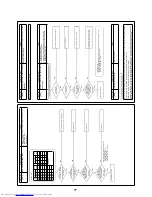
–F
igu
re
(3)
ĺ
If
th
e te
m
p
er
a
tur
e
doe
s n
o
t b
e
co
me
h
ig
h
(
e
quiva
lent
to
ou
tdo
or
te
mp
er
at
ur
e)
, th
e
SV3
F valve
is clogg
ed
.
Re
place
th
e S
V
3F va
lve.
(*2
)Check th
e cl
ogg
ing of th
e
o
il sepa
rator
o
il return circuit
a
nd SV3D.
a)
O
il r
e
turn c
irc
uit
•
W
h
ile
t
h
e
o
u
td
oo
r u
n
it is ru
nn
in
g, che
ck t
h
e
te
mp
era
tur
e
o
n
the
oil
r
e
tu
rn cir
cuit (Ca
p
illa
ry seco
nd
a
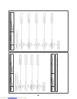
ry).–Fi
gu
re
(
6
)
ĺ
If
the
temp
e
ratu
re
i
s
l
o
w (e
qu
iva
le
nt t
o
ou
tdo
or
t
e
mp
er
atur
e)
, th
e stra
ine
r o
r cap
illa
ry of the
oil
r
e
tu
rn
cir
cuit is
cl
o
gge
d.
R
epl
a
c
e t
he
clo
gg
ed
com
po
ne
nt.
b)
C
heck the SV3D
valve clogging
•
S
e
t [
S
W
0
1
/
SW
02
/
SW
03]
to
[2
/
1
/ 3
]
(7
-se
gm
en
t
display
[Hr
][..
. ..
. .
..])
wh
ile
th
e
out
do
or
u
n
it is
ru
nn
ing,
an
d
the
n
pr
e
ss [SW
0
4] f
o
r 2
seco
nds
or
lon
g
er
.
•
S
e
t [S
W0
2]
to
[9],
an
d t
u
rn
o
n
t
h
e
SV3
D valve
(
7
-s
eg
me
nt
displa
y [Hr
][...
3 d
])
•
If
th
e tem
pe
ra
tu
re
on
t
h
e va
lve
se
con
d
a
ry is lo
w or
d
o
e
s n
o
t cha
ng
e
, the
val
ve, cap
illa
ry, or
stra
in
er
i
s
cl
og
ge
d. –
Figu
re
(7)
R
e
p
lace
the
cl
og
ged
co
mp
on
ent
.
(*3)Ch
eck the
valve
of al
l t
he
outdo
or un
its in
the sa
me
li
ne
(Pe
rfo
rmed
on
ly i
n
the
outdoor unit link
age system
)
a)
Check the SV3A va
lve clogging
•
S
et [SW
0
1
/
SW
02
/
SW
03
] to [2 /
1
/ 3]
(
7
-s
eg
me
nt
disp
la
y
[H
r]
[... ... ...]
) while the
ou
td
oor
unit is
ru
n
n
ing
, and
th
en
p
ress [
S
W
0
4]
for
2
sec
ond
s or
lo
nge
r.
•
S
et
[SW
02
] to
[6
], a
n
d
tur
n
on
SV
3A.
(7
-s
egm
e
n
t
display
[Hr]
[...
3 A
])
•
If th
e t
e
m
p
e
ra
tur
e
on
th
e va
lve
se
cond
ar
y is lo
w
or
do
es n
o
t cha
nge
, t
he
valve
or
clack va
lve m
a
y be
clog
ged
. –
Figu
re
(1)
b)
Check the SV3C valve clo
gging
•
S
et [SW
0
1
/
SW
02
/
SW
03
] to [2 /
1
/ 3]
(
7
-s
eg
me
nt
disp
la
y
[H
r]
[... ... ...]
) while the
ou
td
oor
unit is
ru
n
n
ing
, and
th
en
p
ress [
S
W
0
4]
for
2
sec
ond
s or
lo
nge
r.
•
S
et
[SW
02
] to
[8
], a
n
d
turn
on
SV
3C. (7-se
g
men
t disp
lay [Hr][.
.. 3
C])
•
If t
h
e
tem
p
e
ratu
re
o
n
the
valve
se
cond
ar
y d
o
e
s
n
o
t
chan
ge
(
ri
se
),
th
e
valve
or
str
a
in
e
r m
a
y be
clog
ge
d.
–Figu
re
(
2
)
(*4)
a)
Check the oil circuit cloggin
g
•
O
pe
ra
te
the
ou
tdo
or
u
n
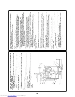
it. (
O
p
e
ra
te
a
ll
the
com
pr
e
ssor
s in t
h
e
un
it
.)
•
A
ft
e
r
o
p
era
ti
n
g
f
o
r
1
0
mi
nu
te
s
or
lon
ge
r,
c
o
n
firm
t
h
at
t
h
e
te
mp
er
at
u
res
o
f t
h
e TK
1,
TK
2,
an
d TK
3
s
e
ns
o
rs
a
n
d
oil
c
ir
c
ui
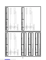
t (Fi
g
u
re
(
8
))
h
a
ve
be
com
e h
igh
.
(Ap
p
roxi
mat
e
gu
ide
)
TK
1,
TK2,
TK3
= Td
1,
Td2,
Td3
te
mp
er
at
ur
e –
10
to
30
°C
O
il
cir
cu
it
: H
ig
h
e
r th
an
sucti
o
n
te
m
per
a
tur
e
or
ou
tdo
or
te
m
per
a
tur
e
•
If
t
h
e
te
mp
er
at
ur
e
is lo
w,
t
h
e
clo
g
g
in
g
of
ca
pil
lar
y
,
str
a
in
e
r,
o
r d
ist
rib
ut
e
r,
or
t
h
e
cla
ck va
lve
op
er
at
io
n
err
or
ma
y ha
ve
o
ccurred
.
Fix th
e e
rro
r.
Cl
a
c
k
v
a
lv
e
Hig
h-
pr
ess
u
re
s
ens
or
Oi
l sepa
rat
or
Check
va
lv
e
Ch
eck
va
lve
Hi
gh-
pres
sure
SW
Hi
gh-
pr
e
ssu
re
SW
C
h
eck
va
lve
Chec
k v
a
lv
e
Co
m
pr
esso
r
1
(Inv
er
te
r)
Co
m
pre
sso
r
2
(In
vert
er
)
Oi
l heade
r
Dis
tr
ibu
ter
Check val
ve
Che
ck val
ve
(6)
(7)
(2)
(5)
(8)
(1)
(4
)
(8
)
Содержание MD-VNK802HEXE
Страница 120: ...118 11Owner s Manual Excerpt ...
Страница 137: ...135 12Installation Manual Excerpt ...

