51
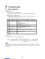
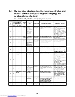
9-2. How to check for errors
The remote controller (local remote controller or central control) is equipped with an LCD that displays the operation
status. If an error has occurred, see the following tables to check the error of the Air to Air Heat Exchanger with DX
Coil Unit using the failure diagnosis function.
The following tables show lists of the check codes indicated by each device. See the following tables for how to
check depending on the location.
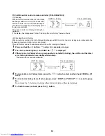
• To check using the indoor remote controller or TCC-LINK central controller…See “Local remote controller &
TCC-LINK central controller” in the following table.
• To check from the outdoor unit...See “7-segment display of outdoor unit” in the following table.
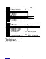
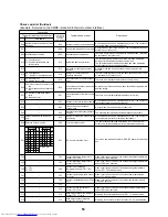
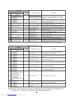
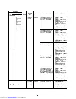
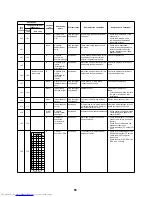
Check code list (Indoor)
(Air to Air Heat Exchanger with DX Coil Unit)
Check code
Typical cause of error
Description
Local remote
controller &
TCC-LINK
central
controller
7-segment display of
outdoor unit
Sub code
E03
–
–
Indoor unit - remote controller regular
communication error
No data is received from the remote controller or network adapter.
(Also no central control communication)
E04
–
–
Indoor unit - outdoor unit regular
communication error
No data is received from the outdoor unit.
E08
E08
Duplicate indoor unit No. Duplicate indoor addresses
The same address was detected.
E10
–
–
Indoor MCU communication error
There is a communication error between the main and motor micro
controller MCU.
E18
–
–
Header indoor unit - Follower indoor unit
regular communication error
Regular communication is not possible between the header and
follower indoor units.
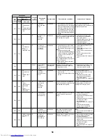
F01
–
–
Indoor heat exchange temperature sensor
(TCJ) error
Open-circuit or short-circuit of the heat exchange temperature
sensor (TCJ) was detected.
F02
–
–
Indoor heat exchange temperature sensor
(TC2) error
Open-circuit or short-circuit of the heat exchange temperature
sensor (TC2) was detected.
F03
–
–
Indoor heat exchange temperature sensor
(TC1) error
Open-circuit or short-circuit of the heat exchange temperature
sensor (TC1) was detected.
F10
–
–
Air temperature sensor (TSA) error
Open-circuit or short-circuit of the air temperature sensor (TSA)
was detected.
F11
–
–
Discharge temperature sensor (TFA) error
Open-circuit or short-circuit of the discharge temperature sensor
(TFA) was detected.
F29
–
–
Indoor unit or other P.C. board error
EEPROM error (Another error may have been detected)
L02
–
–
Outdoor unit model mismatch error
The outdoor unit model is not supported.
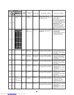
L03
–
–
Duplicate indoor group header unit
settings
There are multiple header units in the group.
L07
–
–
Group line in an individual indoor unit
There are one or more group-connected indoor units.
L08
L08
–
Indoor group address not set
The indoor address group has not been set. (May also be detected
on the outdoor unit)
L09
–
–
Indoor capacity not set
The indoor capacity has not been set.
L20
–
–
Duplicate central control addresses
Central control addresses are duplicate.
L30
L30
Detected indoor unit No.
External error input into indoor unit
(Interlock)
Stopped abnormally due to external error (CN80) input.
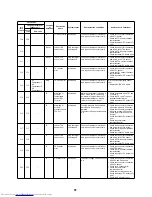
F17
–
–
Outdoor air temperature sensor (TOA)
error
Open-circuit or short-circuit of the outdoor air temperature sensor
(TOA) was detected.
F18
–
–
Return air temperature sensor (TRA) error
Open-circuit or short-circuit of the return air temperature sensor
(TRA) was detected.
P01
–
–
Indoor AC fan error
The indoor AC fan error was detected. (Fan motor thermal relay)
P10
P10
Detected indoor unit No.
Indoor overflow detected
The float switch has worked.
P12
–
–
Indoor DC fan error
The indoor DC fan error (overcurrent, lock, etc.) was detected
P31
–
–
Other indoor unit errors
The group follower unit cannot run due to E03 / L03 / L07 / L08
error of the header unit.
Содержание MD-VNK802HEXE
Страница 120: ...118 11Owner s Manual Excerpt ...
Страница 137: ...135 12Installation Manual Excerpt ...


