39
8-6. Applied control of the indoor unit
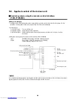
Control system using the remote control interface
(TCB- IFCB4E2)
[Wiring and settings]
• In group control, the system works when connected to any indoor unit (control circuit) in the group. For the
operation / error signals of other units, receive them from the units individually.
(1) Control items
1) ON / OFF input
Turn on / off the unit
2) Operation signal
Output during normal operation
3) Abnormal signal
Output while an alarm is active (Serial communication error or indoor / outdoor
protection)
(2) Diagram of wiring using the remote control interface (TCB- IFCB4E2)
Input
IFCB4E2: Non-voltage, ON / OFF continuous signal
Output
Non-voltage contact (for operation / error display)
Contact capacity: Max. AC 240 V 0.5 A
NOTE
In air-conditioning linkage system, input signals into the header unit (normal indoor unit), and receive only output
signals (operation, alarm) from the Air to Air Heat Exchanger with DX Coil Unit.
Indoor control circuit board
ON / OFF
COM (GND)
Remote controller prohibition / release input
Operation signal output
COM (+12 V)
Abnormal signal output
T10
(Yellow)
ON side
Operation signal input
OFF side
Stop signal input
COM
Operation signal output
Abnormal signal output
TCB-IFCB4E2
Power supply
220 - 240 V
Содержание MD-VNK802HEXE
Страница 120: ...118 11Owner s Manual Excerpt ...
Страница 137: ...135 12Installation Manual Excerpt ...

