203
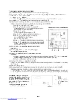
*3 Writing the settings into the EEPROM
(The EEPROM settings on the PC board for service are the factory settings.)
(1) Press and hold the
+
+
buttons for 4 seconds or longer.
1
(this number indicates the one in
"<Remote controller> NRC-01HE")
• The UNIT No.
appears.
The Code (DN)
is displayed. The fan of the Air to Air Heat Exchanger with DX Coil Unit starts running.
(2) Press the
buttons to move up / down through the Codes (DN).
3
(3) Select the model and capacity of the Air to Air Heat Exchanger with DX Coil Unit.
(Changing the model and capacity writes the factory settings into EEPROM.)
1.Change the Code (DN) to
. (As is)
2.Use the
button to select the model.
4
(Select 0050 for the Air to Air Heat Exchanger with DX
Coil Unit. See the table on page 4.)
3.Press the
button.
(Confirm that the indicator lights up.)
5
4.Use the
button to set the Code (DN) to
.
5.Use the
button to select the capacity.
(Ex. Select 0003 for 500 m
3
/h type.
See the table on page 4.)
6.Press the
button. (Confirm that the indicator lights up.)
7.Press the
button to return to the normal stop status.
6
(It takes approximately one minute until you can operate
the remote controller.)
(4) Write the setup data locally specified into the EEPROM.
Repeat Step (1).
(5) Use the
button to set the Code (DN) to
.
(Set the filter sign lighting time)
(6) Compare the setup data with the notes (page 4) and client
information.
1.If the data is different from that of the notes and client information, use the
button to enter data
on the notes, and then press the
button. (Confirm that the indicator lights up.)
2.If the data is the same, go to the next step.
(7) Use the
button to change the Code (DN).
Compare the setup data as in Step (6). Change the setup data according to the notes recorded before replacing
the PC board.
(8) Repeat Steps (6) and (7).
(9) When you have finished setting the data, press the
button to return to the normal stop status.
6
(It takes approximately one minute until you can operate the remote controller.)
• The CODE (DN) is
–
. Some Codes (DN) may be skipped. Even if you change the setting data by mistake and
press the
button, you can recover the setting data by pressing the
button (only before changing the code (DN)).
<EEPROM arrangement figure>
The EEPROM (IC503) is attached to the
IC socket. Use tweezers to remove the
EEPROM. When you attach it to the IC
socket, align the direction as shown in
the figure on the right.
• When you replace the EEPROM, be
careful not to bend the IC wires.
<Remote controller> NRC-01HE
EEPROM
EEPROM
Notch
IC socket
Notch
When attaching
the EEPROM to
the IC socket,
align the notches.
Содержание MD-VNK802HEXE
Страница 120: ...118 11Owner s Manual Excerpt ...
Страница 137: ...135 12Installation Manual Excerpt ...

