background image

REVISION 2 : Mar.2012

Re-edit version.( file volume down)

Contents have NOT been changed.

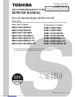
AIR CONDITIONER (MULTI TYPE)

SERVICE MANUAL

FILE No. A10-022-2

Revised Sep. 2011

Air to Air Heat Exchanger with DX Coil Unit

Model name:

Model with a humidifier

MMD-VNK502HEXE
MMD-VNK802HEXE
MMD-VNK1002HEXE
MMD-VNK1002HEXE2
MMD-VNK502HEXE-TR
MMD-VNK802HEXE-TR
MMD-VNK1002HEXE-TR

Model without a humidifier

MMD-VN502HEXE
MMD-VN802HEXE
MMD-VN1002HEXE
MMD-VN1002HEXE2
MMD-VN502HEXE-TR
MMD-VN802HEXE-TR
MMD-VN1002HEXE-TR

  This Service Manual describes contents of the Air to Air Heat Exchanger with DX Coil Unit.

For the outdoor unit, refer to the Manual with FILE NO. A10-005, A05-004-1.

PRINTED IN JAPAN, Sep,  2011, TDOC

Содержание MD-VNK802HEXE

Страница 1: ... VNK502HEXE MMD VNK802HEXE MMD VNK1002HEXE MMD VNK1002HEXE2 MMD VNK502HEXE TR MMD VNK802HEXE TR MMD VNK1002HEXE TR Model without a humidifier MMD VN502HEXE MMD VN802HEXE MMD VN1002HEXE MMD VN1002HEXE2 MMD VN502HEXE TR MMD VN802HEXE TR MMD VN1002HEXE TR This Service Manual describes contents of the Air to Air Heat Exchanger with DX Coil Unit For the outdoor unit refer to the Manual with FILE NO A10...

Страница 2: ... rating 19 7 Control outline 20 8 Applied control and functions including circuit configuration 31 9 Troubleshooting 50 10 Air to Air Heat Exchanger with DX Coil Unit and air conditioning system 115 11 Owner s Manual Excerpt 118 12 Installation Manual Excerpt 135 13 Exchanging and assembling the main components 182 14 How to replace the PC board for service on the Air to Air Heat Exchanger with DX...

Страница 3: ... who have been trained and is thus thoroughly acquainted with the knowledge related to this work The qualified installer who is allowed to work at heights has been trained in matters relating to working at heights with the Air to Air Heat Exchanger with DX Coil Unit made by Toshiba Carrier Corporation or alternatively he or she has been instructed in such matters by an individual or individuals wh...

Страница 4: ...tion for electricians and from heat Work done at heights 50 cm or more Helmets for use in industry Transportation of heavy objects Shoes with additional protective toe cap Indication Explanation DANGER Indicates contents assumed that an imminent danger causing a death or serious injury of the repair engineers and the third parties when an incorrect work has been executed WARNING Indicates possibil...

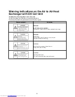
Страница 5: ...lace stick it as the original Warning indication Description WARNING ELECTRICAL SHOCK HAZARD Disconnect all remote electric power supplies before servicing WARNING Moving parts Do not operate unit with inspection cover removed Stop the unit before the servicing CAUTION Do not touch the aluminium fins of the unit Doing so may result in injury CAUTION High temperature parts You might get burned when...

Страница 6: ...ce so that no one will approach the work location before proceeding with the work Parts and other objects may fall from above possibly injuring a person below When executing address setting test run or troubleshooting through the checking window on the electrical control box put on insulated gloves to provide protection from electric shock Otherwise you may receive an electric shock Do not touch t...

Страница 7: ...sition and contact a qualified service person Take steps to ensure that the power will not be turned on by marking out of service near the circuit breaker for instance until qualified service person arrives Continuing to use the Air to Air Heat Exchanger with DX Coil Unit in the trouble status may cause mechanical problems to escalate or result in electric shocks or other failure Electric shock ha...

Страница 8: ...al parts with the electrical control cover of one or more of the indoor units removed in order to find out exactly where the trouble lies put a sign in place so that no one will approach the work location before proceeding with the work Third party individuals may enter the work site and receive electric shocks if this warning is not heeded Insulating measures Connect the cut off lead wires with c...

Страница 9: ... fan heater stove or cocking stove though the refrigerant gas itself is innocuous Never recover the refrigerant into the outdoor unit When the equipment is moved or repaired be sure to recover the refrigerant with recovering device The refrigerant cannot be recovered in the outdoor unit otherwise a serious accident such as breakage or injury is caused Assembly Wiring After repair work surely assem...

Страница 10: ...tion or unsteadiness and the installation is stable If check is not executed a fire an electric shock or an injury is caused When carrying out the pump down work shut down the compressor before disconnecting the refrigerant pipe Disconnecting the refrigerant pipe with the service valve left open and the compressor still operating will cause air etc to be sucked in raising the pressure inside the r...

Страница 11: ...ely purchased parts Use of non specified products may result in fire electric shock water leakage or other failure Have the installation performed by a qualified installer Do not supply power from the power terminal block equipped on the outdoor unit to another outdoor unit Capacity overflow may occur on the terminal block and may result in fire Do not install the Air to Air Heat Exchanger with DX...

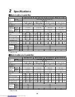
Страница 12: ...39 0 41 0 38 0 39 0 42 0 41 0 39 0 42 5 41 0 39 0 Sound power level dBA External dimensions Height mm 430 430 Width mm 1140 1189 Depth mm 1690 1739 Weight kg 91 111 112 114 MMD VN502HEXE MMD VN802HEXE MMD VN1002HEXE MMD VN1002HEXE2 Type Function Cooling and heating dual purpose type Unit configuration Discrete type Voltage 220 240 V 50 Hz 220 V 60 Hz 220 240 V 50 Hz 220 V 60 Hz 220 240 V 50 Hz 220...

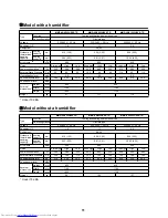
Страница 13: ...35 5 33 5 40 0 39 0 38 0 42 0 41 0 39 0 Sound power level dBA External dimensions Height mm 430 430 Width mm 1140 1189 Depth mm 1690 1739 Weight kg 91 111 112 MMD VN502HEXE TR MMD VN802HEXE TR MMD VN1002HEXE TR Type Function Cooling and heating dual purpose type Unit configuration Discrete type Voltage 220 240 V 50 Hz 220 240 V 50 Hz 220 240 V 50 Hz Equivalent HP 1 0 1 7 2 0 Refrigerant R410A Outd...

Страница 14: ...Exchanger with DX Coil Unit Model type MMD VNK502HEXE MMD VNK502HEXE TR MMD VNK802HEXE MMD VNK802HEXE TR MMD VNK1002HEXE MMD VNK1002HEXE TR MMD VNK1002HEXE2 MMD VN502HEXE MMD VN502HEXE TR MMD VN802HEXE MMD VN802HEXE TR MMD VN1002HEXE MMD VN1002HEXE TR MMD VN1002HEXE2 Commercial name TOSHIBA Air to Air Heat Exchanger with DX Coil Unit Complies with the provisions of the Machinery Directive Directiv...

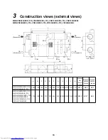
Страница 15: ... Refrigerant pipe size Liquid side MMD VNK502HEXE TR MMD VN502HEXE TR 1 690 1 140 1 140 250 175 350 175 Ø195 Ø212 1 601 1 197 Ø200 Ø9 5 Ø6 4 MMD VNK802HEXE TR MMD VN802HEXE TR MMD VNK1002HEXE TR MMD VNK1002HEXE2 MMD VN1002HEXE TR MMD VN1002HEXE2 1 739 1 189 1 189 275 200 400 200 Ø245 Ø262 1 650 1 246 Ø250 Ø12 7 Ø6 4 EA Exhaust air RA Return air OA Outdoor air SA Supply air TRA TOA TSA TFA A J G E ...

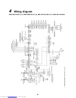
Страница 16: ...e Red RY708 RY709 RY710 Indoor control circuit board MCC1615 Power supply DC 20 V DC 15 V DC 12 V DC 7 V SW701 CN760 White DAM Blue Yellow White Red Purple TB3 External output 220 V under 1 A each Operation output Common External damper output Abnormal Bypass mode output CN704 CN705 CN706 CN61 Yellow CN81 Black CN82 Blue Common Remote controller operation Fan speed Operation 5 External input Optio...

Страница 17: ...e when using a voltage of DC 12 V or 24 V 6 Orange wire High is connected as factory default To switch to Extra High connect black wire s connector instead of orange Code Parts name Code Parts name Code Parts name CN Connector TFA TFA sensor DMV1 Decompression magnetic valve F01 Fuse printed circuit board TCJ TC1 TC2 Indoor coil sensor PMV Pulse modulating valve F02 Fuse motor TB1 Terminal block p...

Страница 18: ...ge Blue Red Orange Blue Red RY708 RY709 RY710 Indoor control circuit board MCC1615 Power supply DC 20 V DC 15 V DC 12 V DC 7 V SW701 CN760 White DAM Blue Yellow White Red Purple TB3 External output 220 240 V under 1 A each Operation output Common External damper output Abnormal Bypass mode output CN704 CN705 CN706 CN61 Yellow CN81 Black CN82 Blue Common Remote controller operation Fan speed Operat...

Страница 19: ...ontact DC 12 V 1 mA In addition ON OFF operation is possible when using a voltage of DC 12 V or 24 V 6 Orange wire High is connected as factory default To switch to Extra High connect black wire s connector instead of orange Code Parts name Code Parts name Code Parts name CN Connector TSA TSA sensor SW701 Dip switch F01 Fuse printed circuit board TFA TFA sensor 43F11 43F12 Relay for air supplying ...

Страница 20: ...0 3P Brown 1 For Super heat control in cooling 2 TC2 Connector CN101 2P Black 1 For Under cool control in heating 3 TCJ Connector CN102 2P Red 1 For Super heat control in cooling 4 TFA Connector CN103 2P Green 1 For discharge temperature detection 5 TSA Connector CN104 2P Yellow 1 For detecting Air Suction Temperature of direct expansion coil Liquid side Gas side Strainer Pulse modulating valve Ca...

Страница 21: ...r fan motor 450 V 5 ȝF 450 V 10 ȝF 450 V 5 ȝF 450 V 10 ȝF TOA sensor Ø6 size lead wire length 1 400 mm vinyl tube Blue TC1 sensor Ø4 size lead wire length 1 200 mm non migratory tube Blue TC2 sensor Ø6 size lead wire length 1 200 mm vinyl tube Blue TCJ sensor Ø6 size lead wire length 1 200 mm vinyl tube Red TRA sensor Ø5 size lead wire length 1 270 mm non migratory tube Black TSA sensor Ø5 size le...

Страница 22: ...ration When using the external signals use the terminal of the header unit normal indoor unit CODE No 31 3 Operation switch 1 The operation is switched by the request from the remote controller The AUTO mode cannot be selected for the Air to Air Heat Exchanger with DX Coil Unit 2 When CODE 31 Single operation of ventilation is set to 1 Possible in air conditioning linkage system the Air to Air Hea...

Страница 23: ...6 C9 CA Heat suction temperature shift Except during remote controller thermo Follow the normal indoor unit setting No Item Specification outline Remarks SET DATA 2 3 Ventilation mode Heat exchange Automatic By remote controller Description High Operate supply air exhaust air in High Low Operate supply air exhaust air in Low Unbalance Operate supply air in High exhaust air in Low Supply air Exhaus...

Страница 24: ...rigerant oil collecting is performed or after the operation is finished 2 The fan is stopped during heat refrigerant collecting when the cooling or fan operation is selected The fan continues running during cool refrigerant collecting when the heating operation is selected The forced fan OFF control is given priority TFA Discharge temperature 10 Forced thermo OFF 1 The thermo is turned off forcedl...

Страница 25: ...epending on the temperature TRA TOA TSA Condition 1 or 2 is met while Condition 3 is not The fan OFF is continued for 60 minutes the fan is operated for 5 minutes and then the forced fan OFF is continued or released depending on the temperature TRA TOA TSA 3 The cooling zone is determined as follows depending on the relation between TRA and TOA 1 Condition of switch to Zone A Zone B ĺ Zone A TOA 8...

Страница 26: ...he operation mode and TRA TOA and TSA 1 Fan 2 Cool No Item Specification outline Remarks TOA Outdoor air temperature C TRA Return air temperature C Heat exchange Heat exchange Undefined zone Undefined zone Bypass Bypass TOA Outdoor air temperature C TRA Return air temperature C Heat exchange Undefined zone Bypass Temperature setting 25 C ...

Страница 27: ...pending on the temperature detected by TC1 TC2 or TCJ sensor The thermo is turned off forcedly if the J zone is detected for 5 minutes The timer count is stopped and retained when in K zone If the I zone is detected the timer is cleared and the normal operation restarts If the thermo is turned off forcedly to maintain the J zone only the fan is operated until it enters the I zone Recovered in the ...

Страница 28: ...operation stops the fan and displays Prep The collecting operation is usually performed every hour 17 Nighttime heat purge This function is valid only for the Air to Air Heat Exchanger with DX Coil Unit system linked with air conditioners Invalid for Air to Air Heat Exchanger with DX Coil Unit system 1 If the ON OFF button is pressed during operation the Air to Air Heat Exchanger with DX Coil Unit...

Страница 29: ...heat purge operation start of temperature monitoring operation 8 When nighttime heat purge operation stops the Nighttime heat purge display goes out 18 Humidifying control 1 The heating operation automatically turns on the magnetic valve to perform the humidifying operation 2 Magnetic valve ON conditions The operation mode is Heating default Air Suction Temperature of direct expansion coil TSA Į C...

Страница 30: ...CODE DN 40 19 Drain pump control 1 The drain pump is always operated in Cooling mode or Drying mode 2 When the cooling or drying operation is stopped the drain pump is not immediately stopped but continues running for other 5 minutes in order to drain water from the drain pan 3 If the float switch works when the drain pump is running the check code appears 4 If the float switch works when the drai...

Страница 31: ... time 2500 H has passed send the filter replacement signals to the remote controller and display it on LCD 2 When the filter reset signals are received from the remote controller the accumulated timer is cleared If a given time has already passed the calculated time is reset and the LCD display disappears Filter lights up 24 Prep Operation Prep Heat display Prep Operation Displayed on the remote c...

Страница 32: ...t for the following OFF when the nighttime heat purge operation is stopped temporarily CODE No 5C 27 Power saving mode 1 Performed when the SAVE button on the remote controller is pressed 2 The SAVE segment lights up on the wired remote controller display in saving operation 3 The requirement capacity ratio is limited to the following in saving operation 4 If the power saving operation is enabled ...

Страница 33: ...an motor Humidifier Drain pump Fan motor relay circuit Fan motor relay circuit Relay circuit Relay circuit Power supply circuit Remote controller communication circuit EEPROM MCU Driver External output Driving Damper Abnormal External input Remote controller invalid High Low Bypass Heat Exchange ON OFF AC synchronous signal input circuit TC1 sensor TC2 sensor TCJ sensor TFA sensor TSA sensor TRA s...

Страница 34: ... CN104 yellow TFA sensor CN103 green TCJ sensor CN102 red TC2 sensor CN101 black TC1 sensor CN100 brown External input abnormal CN80 green DC12 V Float SW drain up CN634 red DC12 V Float SW CN34 red DC12 V PMV output CN82 blue DC12 V Central control communication LED D503 yellow Remote controller communication LED D504 green Connectors for the external input CN705 red Damper motor CN760 white DC12...

Страница 35: ...eat exchange is selected The bypass is always performed when Automatic is selected 4 Perform Steps 4 and 5 in the above Starting and stopping test operation to release the test operating mode Procedure Operation 1 When the TEST button is pressed for 4 seconds or longer TEST appears in the display section and the unit enters the test operating mode 2 Press the ON OFF button 3 Press the MODE button ...

Страница 36: ... resumes automatically in several minutes When replacing the PMV coil apply the maximum opening For the detailed positions of CHK pin CN71 on P C board and DISP pin CN72 on P C board refer to the Indoor Printed Circuit Board MCC 1615 on page 32 Indoor unit exhibition mode of the indoor unit This function can be used when you use the indoor unit and remote controller only in an exhibition etc The g...

Страница 37: ...e static input changed by No 2 of DIP SW701 OFF Pulse default ON Static The setting is opposite to that of the external input 2 0 V COM 3 Remote controller prohibition input Remote controller prohibition input ON Prohibited OFF Allowed 4 Operation output ON during operation answer back of HA 5 DC12 V COM 6 Alarm output ON during alarm FILTER Optional abnormal humidifier setting CN70 1 Switching op...

Страница 38: ...roup control Only the fan of the selected indoor unit starts running 3 Use the button to select the Code DN 4 Use the button to select the setting 5 Press the button Confirm that the indicator lights up To change the selected indoor unit go back to 2 To change CODE No DN to set go back to 3 6 Press the button to return to the normal stop status NOTE To change the function of the indoor unit when l...

Страница 39: ... humidifier 0001 Humidifier Depends on the type 47 Ventilation fan speed during nighttime heat purge operation 0000 Always LOW 0001 Operate at ventilation fan speed set last time the operation was stopped 0000 Always LOW 48 Unbalanced fan speed ventilation 0000 Invalid 0002 SA EA 0001 SA EA 0000 Invalid 4C Nighttime heat purge setting 0000 Invalid 0001 Start in 1 hour 0048 Start in 48 hours 0000 I...

Страница 40: ... a humidifier Code 40 Factory setting of EEPROM stored on the PC board for service SET DATA Model Model name abbreviation 0050 Air to Air Heat Exchanger with DX Coil Unit MMD VNK series MMD VN series Higher SET DATA Type 0000 Invalid 0003 500 m3 h type 0007 800 m3 h type 0009 950 m3 h type Higher SET DATA Type 0000 No MMD VN series 0001 Yes MMD VNK series Higher ...

Страница 41: ...tection 2 Diagram of wiring using the remote control interface TCB IFCB4E2 Input IFCB4E2 Non voltage ON OFF continuous signal Output Non voltage contact for operation error display Contact capacity Max AC 240 V 0 5 A NOTE In air conditioning linkage system input signals into the header unit normal indoor unit and receive only output signals operation alarm from the Air to Air Heat Exchanger with D...

Страница 42: ... card is removed from the card switch box If the above contact operation is not performed in the card switch box convert it by b contact relay 2 Operation Follow the procedure below on the wired remote controller Perform while the unit is stopped 1 Press and hold the button button button for 4 seconds or longer 2 Use the button to set the Code DN to 3 Use the button to set the setting to 4 Press t...

Страница 43: ...et the Air to Air Heat Exchanger with DX Coil Unit as the header 1 Make a pair of the indoor unit and remote controller 2 Turn on the power 3 Press and hold the button button button for 4 seconds or longer The LCD starts blinking Line address 4 Use the button to set the Code DN to 5 Use the button to set the line address The address must be the same as the line address of the center unit interface...

Страница 44: ... group control the UNIT No of another unit appears each time the button is pressed 2 When you want to know the indoor unit position by the address Checking the UNIT No in the group control Procedure Perform while the unit is stopped The indoor unit No appear one by one in the group control The fan of the indoor unit starts running 1 Press and hold the button button for 4 seconds or longer The UNIT...

Страница 45: ...nd CODE No Address Change appear at first Select an outdoor unit 2 Press or to select the line address 3 Press the button to confirm the selected line address Displays the address of the indoor unit connected to the refrigerant pipe of the selected outdoor unit The fan of the indoor unit starts running 4 Press the button to display the indoor unit No one by one in the same piping Only the fan of t...

Страница 46: ...button button button for 4 seconds or longer The first displayed UNIT No is the header unit address if in the group control 2 Press the button to select an indoor unit No if in the group control The fan of the selected indoor unit starts running 3 Use the button to set CODE No to 4 Use the button to change the displayed data 5 Press the button 6 Press the button to select an indoor unit No to chan...

Страница 47: ...he refrigerant pipe of the selected outdoor unit The fan of the indoor unit starts running The current indoor address appears in SET DATA The line address does not appear 4 Use the button to change the indoor address displayed in SET DATA Change it to a new address 5 Press the button to confirm 6 Press the button to display the indoor unit No one by one in the same piping Only the fan of the selec...

Страница 48: ... the button button for 4 seconds or longer to enter the service monitoring mode 2 Press the button to set CODE No to FF 3 The display in A of the following figure counts down as follows at 5 second intervals 0005 ĺ 0004 ĺ 0003 ĺ 0002 ĺ 0001 ĺ 0000 The error is cleared when 0000 appears However the display counts down from 0005 again 4 Press the button to return the display to normal Clearing an er...

Страница 49: ...outdoor unit in the refrigerant line 4 Press the button to return the display to normal 1 In the case of group connection only the header indoor unit data can be displayed CODE No Data Format Unit Remote controller display example Indoor unit data 00 Room temperature in control 1 x 1 C 0024 24 C 01 Room temperature Remote controller x 1 C 02 Return Air Temperature TRA x 1 C 03 Coil Temperature TCJ...

Страница 50: ...ent of compressor 1 I1 x 10 A 0135 13 5 A 1D 2D 3D 4D Current of compressor 2 I2 x 10 A 1E 2E 3E Current of compressor 3 I3 x 10 A 1F 2F 3F 4F Outdoor fan current IFan x 10 A CODE No Data Format Unit Remote controller display example U1 U2 U3 U4 Individual data of outdoor unit 3 50 60 70 80 Rotation of compressor 1 x 10 rps 0642 64 2 rps 51 61 71 81 Rotation of compressor 2 x 10 rps 52 62 72 Rotat...

Страница 51: ...o the remote controller 3 D503 Yellow Indoor Outdoor central control Lights up for the first half 5 seconds while communicating with a central control device Blinks for the second half 5 seconds at 0 2 second intervals 0 1 second while communicating with the outdoor unit 4 D504 Green Remote controller communication The group header unit lights up for the first half 5 seconds while communicating wi...

Страница 52: ... noise source shield the remote controller wires and signal wires No Symptom Check 1 The compressor does not run During 3 minute delay within 3 minutes after the compressor is turned off Is the thermo off During fan or timer operation During initial communication of the system In Bypass mode 2 The indoor fan does not run Is the indoor outdoor temperature out of range During forced fan OFF control ...

Страница 53: ... heat exchange temperature sensor TC2 error Open circuit or short circuit of the heat exchange temperature sensor TC2 was detected F03 Indoor heat exchange temperature sensor TC1 error Open circuit or short circuit of the heat exchange temperature sensor TC1 was detected F10 Air temperature sensor TSA error Open circuit or short circuit of the air temperature sensor TSA was detected F11 Discharge ...

Страница 54: ...E09 Duplicate header remote controllers Two remote controllers are set as header in the double remote controller control The header indoor unit stops signaling an error and the follower indoor units continue running Check code Typical cause of error Description TCC LINK central controller 7 segment display of outdoor unit Sub code C05 Central control communication transmission error No central con...

Страница 55: ...nits decreasing No communication can be established any more The number of connected thermal units has decreased E23 E23 Transmission error between outdoor units No signal can be sent to another outdoor unit E25 E25 Duplicate terminal outdoor address settings The manually set terminal outdoor addresses are duplicate E26 Outdoor address with reception error E26 Number of connected outdoor units dec...

Страница 56: ...or line addresses There are duplicate settings of the line address for outdoor units of different refrigerant piping lines L06 Number of prior indoor units L05 L06 individually displayed L05 Duplicate prior indoor Displayed for prior indoor There are multiple prior indoor units For prior indoor unit L06 Duplicate prior indoor Displayed for non prior indoor There are multiple prior indoor units For...

Страница 57: ...e criteria P24 Detected thermal unit No P24 Thermal unit error Code The thermal unit detected an error The thermal remote controller displays detailed check code in addition to the unit No Check code Typical cause of error Description 7 segment display of outdoor unit Local remote controller TCC LINK central controller Sub code F13 01 Compressor 1 02 Compressor 2 03 Compressor 3 F13 Outdoor IGBT b...

Страница 58: ...error history can be checked even while the unit is running or stopped Procedure Perform while the unit is stopped 1 Press and hold the button button for 4 seconds or longer to enter the service check mode The service check lights up The CODE No and latest alarm appear The alarmed UNIT No and its content appear 2 To monitor other error history press the buttons to change the error history No CODE ...

Страница 59: ...e error history can be checked even while the unit is running or stopped 1 Press and hold the button button for 4 seconds or longer 2 The service check lights up and CODE No is displayed 3 If there is an error history when a group number is selected blinking the unit No and the latest error history information are displayed alternately The temperature cannot be adjusted 4 To check other error hist...

Страница 60: ...or unit Check the order of central power on Check indoor address settings Check indoor outdoor wiring Check outdoor terminal resistance settings SW30 Bit 2 E06 E06 Number of indoor units for normal reception I F Number of indoor units decreasing All stopped Signals are not returned for a given time from the indoor unit Check indoor unit power Whether powered on Check the connection of the communic...

Страница 61: ...E19 E19 00 No center unit 02 Multiple center units I F Unusual number of center outdoor units All stopped There are multiple center outdoor units in a line There are no center outdoor units in a line The center outdoor unit is connected to the indoor outdoor wiring U1 U2 Check the connection of the communication line between indoor and outdoor Check the outdoor PC board I F error E20 E20 01 Outdoo...

Страница 62: ...rror Only the target unit stopped The sensor resistance is infinite or zero open circuit or short circuit Check the connector connection and wiring of the TC1 sensor Check the TC1 sensor resistant characteristics Check the indoor PC board error F04 F04 I F TD1 sensor error All stopped The sensor resistance is infinite or zero open circuit or short circuit Check the connector connection of the TD1 ...

Страница 63: ...ristics Check the outdoor PC board I F error F16 F16 I F Miswiring of outdoor pressure sensor Pd Ps All stopped The high pressure Pd sensor and low pressure Ps sensor are replaced The output voltage of both sensors is 0 Check the connector connection of the high pressure Pd sensor Check the connector connection of the low pressure Ps sensor Check the pressure sensor Pd Ps error Check the outdoor P...

Страница 64: ...connection of the A3 IPDU board Check case heater conduction Activation error due to liquid hibernation in the compressor Check the outdoor PC board A3 IPDU error H03 H03 01 Compressor 1 02 Compressor 2 03 Compressor 3 IPDU Current detection circuit error All stopped Overcurrent was detected while the inverter compressor is stopped Check current detection circuit wiring Check the outdoor PC board ...

Страница 65: ... connection of the TK2 sensor Check the TK2 sensor resistant characteristics Check the outdoor PC board I F error All stopped The sensor resistance is infinite or zero open circuit or short circuit Check the connector connection of the TK3 sensor Check the TK3 sensor resistant characteristics Check the outdoor PC board I F error All stopped The sensor resistance is infinite or zero open circuit or...

Страница 66: ...Check the hibernating refrigerant in compressor The temperature change of TK4 cannot be detected even after Compressor 4 starts operating Check the TK4 sensor installation Check the TK4 sensor resistant characteristics Check the misconnection of TK1 TK2 TK3 TK4 or TK5 Check the SV3E and SV3F valve error Check the oil circuit capillary clogging and non return valve error Check the hibernating refri...

Страница 67: ...topped Address not set Check indoor addresses Note This code appears the first time the power is turned on after installation L09 Indoor Indoor capacity not set Only the target unit stopped The indoor capacity has not been set Set the indoor capacity DN 11 L10 L10 I F Indoor capacity not set All stopped A jumper line for the model was not cut on the dedicated PC board for the PC board I F service ...

Страница 68: ...an error Check the outdoor fan motor error Check the outdoor PMV clogging PMV1 2 Check the heat exchanger clogging Short circuit of the outdoor suction discharge air Check the SV2 circuit clogging Check the outdoor PC board I F error Check indoor fan error caused by low air volume Check the opening status of indoor PMV Check the miswiring of the communication line between indoor and outdoor Check ...

Страница 69: ... F Gas leak detection TD condition All stopped Protective stop performed when the compressor is running in low frequency and the discharge temperature TD1 TD2 or TD3 is over 108 C for 10 minutes is repeated 4 times or more Check the refrigerant shortage Check the outdoor PMV clogging PMV1 2 Check the TD1 TD2 or TD3 sensor resistant characteristics Check the indoor filter clogging Check the pipe cl...

Страница 70: ... blowing and obstacles Position detection is not performed properly Check the fan motor Check the error of IPDU board for fan All stopped Sub code 4 FAN IPDU overcurrent protection circuit Overcurrent was detected while the fan is running Check the fan motor Check the connector connection for fan motor Check the error of IPDU board for fan All stopped Sub code C The TH sensor temperature is over a...

Страница 71: ...ive signals Check central control device errors Check central control wiring errors Check terminal resistance setting Check central control connection power source Check central control connection PC board errors C12 General purpose device I F General purpose control device control Interface simultaneous alarms Operation continues Error input was detected for general purpose device control interfa...

Страница 72: ...or coil resistance 1 Shut down the power 2 Remove the leads from the compressor 3 Use the tester to check the coil resistance between the phases of each compressor and the outdoor box resistance Does grounding occur ĺ There is no problem if it is 10 Mȍ or higher Does a short circuit occur between the coils ĺ There is no problem if it is 0 1 ȍ 0 4 ȍ Check with the digital tester Checking the outdoo...

Страница 73: ...gain Check the indoor board Error ĺ Replace Set either of the remote controller as the header Remote controller address connector Check remote controller board Error ĺ Replace Cause No signal can be sent to the indoor unit This code is not displayed on the central control device or outdoor 7 segment displayed Cause No communications from the remote controller and network adapter wiring This error ...

Страница 74: ...oor outdoor wiring is connected properly and then connect the wiring connector on the indoor unit board from CN40 to CN44 EMG Check and remove the noise etc For details see Troubleshooting for test run Cause 1 Indoor outdoor communication wiring U1 U2 connection error 2 Connection error of connector for indoor communications PC board error 3 Connection error of connector for outdoor communications...

Страница 75: ...d Yes Outdoor I F board error ĺ Replace Correct the wiring Correct the power wiring Check the conduction using the tester Remove the noise I F board error However the unit can be temporarily run by inserting the connector for CN01 into CN33 Power on and start running Cause Duplicate indoor addresses Check code name Duplicate indoor addresses Check code E08 Is the wiring connection correct Is the w...

Страница 76: ...rror ĺ Replace Connection between U1 U2 and U3 U4 No Yes Configure the address setting again See Address setting procedure Disconnect the connection between U1 U2 and U3 U4 Auxiliary code 01 Indoor Outdoor communications 02 Communications between outdoor units Turn on the outdoor unit again Cause 1 Indoor outdoor communication wiring connection error 2 Indoor power line error 3 Peripheral noise 4 ...

Страница 77: ...ed Correct the miswiring Correct the horse power setting Set the total capacity of connected indoor units to 135 or lower Set the horse power of the outdoor unit See Procedure for replacing the interface board 1 No over capacity detect setting Turn on SW09 Bit 2 on the center outdoor I F board Usually turned off Cause Regular communication is not possible between the header and follower indoor uni...

Страница 78: ...er unit is connected to the indoor outdoor wiring U1 U2 Auxiliary code 00 Another line outdoor unit 02 Another line indoor unit Cause 1 Outdoor wiring connection error 2 Connection error of connector for outdoor communications I F board error 3 Outdoor communication terminal resistance setting error Check code name Transmission error between outdoor units Check code E23 Is there any miswiring disc...

Страница 79: ... the I F board 1 Clearing an error Set SW01 SW02 SW03 on the I F board of the center outdoor unit to 2 16 1 and then press SW04 for 5 seconds or longer 7 segment display Er CL No Yes No Yes Is the terminal unit turned on Is the communication connector CN03 between outdoor units of the terminal unit connected correctly Turn on the power Correct the wiring connection Correct the connector connection...

Страница 80: ...it temperature sensor characteristics If the sensor is working properly replace the outdoor I F board Cause TD2 sensor open circuit short circuit The TD2 sensor open circuit short circuit was detected Check the disconnection of the connector connection circuit TD2 sensor CN503 Pink or sensor resistance value characteristics See 9 9 Sensor characteristics Outdoor unit temperature sensor characteris...

Страница 81: ...e TS1 sensor open circuit short circuit was detected Check the disconnection of the connector connection circuit TS1 sensor CN505 White or sensor resistance value characteristics See 9 9 Sensor characteristics Outdoor unit temperature sensor characteristics If the sensor is working properly replace the outdoor I F board Check code name TL sensor error Check code name TO sensor error Check code nam...

Страница 82: ...1 2 2 Check the compressor 1 Pressure by pressure gauge Check joint 2 Pressure display in 7 segment 3 Output voltage of the I F board If 1 is different from 2 and 3 an error may have occurred on the pressure sensor If 2 and 3 are different check the interface board Cause TD3 sensor open circuit short circuit The TD3 sensor open circuit short circuit was detected Check the disconnection of the conn...

Страница 83: ...essor circuit error 3 Compressor error 4 Overload operation 5 A3 IPDU board error Check code name Compressor breakdown Rotor stop conduction Check code H01 Is the voltage of the outdoor unit correct 1 No Yes Check the A3 IPDU board Yes No No Yes Is the wiring connector connection on the A3 IPDU board correct Is the coil resistance between the phases of the target compressor correct 2 Correct power...

Страница 84: ... or during operation 1 Rating voltage 10 Auxiliary code 01 Compressor 1 02 Compressor 2 03 Compressor 3 Yes No Yes No Does the voltage decrease when another compressor starts running Is the refrigerant hibernating in the compressor case Correct the wiring connector connection Correct the overload Correct the hibernating refrigerant in the compressor case Check the A3 IPDU board No Yes Is the compr...

Страница 85: ...se 1 Balance pipe valve closed All outdoor units in the same line 2 Miswiring Misinstallation of TK1 to TK5 sensor 3 TK1 to TK5 sensor error 4 Gas and oil leakage in the same line 5 Hibernating refrigerant in compressor case 6 Error of SV3A 3B 3C 3D 3E 3F 7 Clogging of the oil separator oil return circuit 8 Oil circuit clogging Check code name Lower oil level detection protection Check code H07 Is...

Страница 86: ...ot change any more f Check the SV3F valve clogging Set SW01 SW02 SW03 to 2 1 3 7 segment display Hr while the outdoor unit is running and then press SW04 for 2 seconds or longer Set SW02 to 8 and turn on SV3C SV3E and SV3F 7 segment display Hr 3 C While the outdoor unit is running check the temperature change on the SV3F valve secondary Figure 3 ĺ If the temperature does not become high equivalent...

Страница 87: ...4 TK4 sensor error 05 TK5 sensor error Has the TK1 sensor removed Yes No Check the I F board Yes No No Yes Is there miswiring misinstallation of TK1 to TK5 sensors Check the SV3E valve clogging 1 Install the sensor properly Fix the miswiring misinstallation TK1 CN531 Black TK2 CN532 Green TK3 CN533 Pink TK4 CN534 Yellow TK5 CN535 Red Replace the clogged component See 9 9 Sensor characteristics Ind...

Страница 88: ...ted Replace the SV3E valve Error detected Compressor 2 Strainer Capillary TK2 After the power is reset Cause 1 TK3 sensor removed miswiring resistant characteristics error 2 Oil circuit error clack valve capillary strainer clogging 3 Hibernating refrigerant in compressor case Check code name Oil detection circuit error TK3 temperature detection circuit error Auxiliary code 03 Check code H16 Has th...

Страница 89: ...sensor temperature If the temperature continues low equivalent to outdoor temperature or does not change the clogging of the parallel capillary may have occurred No error No error 1 See the H07 error Sensor error ĺ replace Error detected Replace the SV3E valve Error detected Strainer SV3C valve TK4 After the power is reset Check the clogging of the SV3C valve bypass capillary Cause 1 TK5 sensor re...

Страница 90: ...door unit model mismatch error Check code name Duplicate header indoor units Check code name Duplicate outdoor line address settings Check code name Duplicate prior indoor Displayed on prior indoor Check code L02 Check code L03 Check code L04 Check code L05 Duplicate line addresses Yes No Check the outdoor I F board Error ĺ Replace No Yes Is the wiring connection of U1 U2 U3 U4 and U5 U6 correct C...

Страница 91: ...oor unit again Yes No Is the indoor capacity setting wrong Set the indoor capacity data Code DN 11 Check the indoor board Error ĺ Replace Cause SMMS i SMMS 4 series is connected to an outdoor unit of 3 series or older SMMS i SMMS 4 series cannot be connected to an outdoor unit of 3 SMMS series or older Use an outdoor unit combination of SMMS i only Cause Duplicate central control addresses Cause 1...

Страница 92: ... pin GND Correct the connector connection Replace the wire I F board error No Yes Is there voltage swing between 3 and 5 of CN600 on the I F board Tester calculation DC 0 to 5 V 5 pin GND I F board error Cause External input abnormal Cause 1 Outdoor power supply error 2 Outdoor I F board error Cause 1 Wiring error 2 Fan motor check Check code name External interlock for indoor unit Check code name...

Страница 93: ...refrigerant again Cause 1 High pressure SW error 2 Service valve closed 3 Pd sensor error 4 Indoor Outdoor fan error 5 Indoor Outdoor PMV clogging 6 Heat exchanger clogging short circuit 7 SV2 circuit error 8 SV4 circuit error 9 SV5 circuit error 10 Discharge check valve error 11 Refrigerant overcharging Check code name High pressure SW error Check code P04 Reset the power and then start the test ...

Страница 94: ...ce the PMV Check and correct wiring Replace the TC2 or TCJ sensor Cause The power supply to the outdoor unit is open phased or stopped Check the open phase of the outdoor unit power supply wiring Check the error of the outdoor I F board Check if the terminal is tightened firmly etc Cause 1 Power supply voltage error 2 Outdoor fan error 3 Heat sink installation error 4 Heat sink cooling duct cloggi...

Страница 95: ...heck valve leakage in the discharge area 6 Outdoor I F board error Check code name Outdoor compressor liquid compression error Check code P13 Check the I F board No Yes Is the outdoor PMV1 PMV2 PMV4 connector connection correct Correct the connector connection PMV1 CN300 PMV2 CN301 PMV4 CN303 No Yes Is the outdoor PMV1 PMV2 PMV4 working properly Are Pd and Ps sensor output voltage characteristics ...

Страница 96: ...Confirm that there is no clogging or broken pipe and then charge the refrigerant again Cause 1 Outdoor service valve closed 2 Outdoor PMV 3 TD sensor error 4 SV4 circuit error 5 Refrigerant shortage Pipe clogging Check code name Gas leak detection TD condition Auxiliary code 02 Check code P15 Refrigerant shortage Clogging Broken pipe No Yes Are the gas pipe liquid pipe and service valve of the out...

Страница 97: ... Check the four way valve Fix the valve coil misinstallation Replace the SV42 valve Correct the wiring Cause 1 Outdoor service valve closed 2 Outdoor PMV error 3 TD sensor error 4 Refrigerant shortage Pipe clogging 5 Four way valve error 6 SV4 circuit leakage misinstallation Check code name Discharge temperature TD3 error Check code P18 Refrigerant shortage Clogging Broken pipe No Yes Are the gas ...

Страница 98: ...ndoor Outdoor PMV clogging 5 Heat exchanger clogging 6 SV2 circuit error 7 SV4 circuit error 8 SV5 circuit error 9 Outdoor I F board error 10 Discharge check valve error 11 Refrigerant overcharging Check code name High pressure protection activation Check code P20 Is the fan proper No Yes Is the service valve opened fully Are the high pressure sensor characteristics correct Does the outdoor fan of...

Страница 99: ...eck valve in the discharge area Remove the obstacles Replace the PMV Fix the SV5 circuit Coil error Clogging Broken pipe etc Check and correct wiring Replace the TC2 or TCJ sensor Cause 1 Fan lock 2 Fan IPDU board error 3 Overload 4 External factors such as blast Check code name Outdoor fan IPDU error Check code P22 Is the wiring connector connection on the Fan IPDU board correct No Yes Correct th...

Страница 100: ...error 2 Compressor error 3 A3 IPDU board error Cause Another indoor unit in the group is malfunctioning The E03 L03 L07 L08 error detected on the header unit in the group leads to the P31 error on the follower and the unit stops The check code does not appear on the remote controller or is not recorded in the alarm history Check code name Compressor position detection circuit error Check code name...

Страница 101: ...splayed on the right side of the 7 segment display U1 Check code Switch setting for checking the check code Set SW01 SW02 SW03 to 1 1 1 If there is also an auxiliary code the check code appears for 3 seconds and the auxiliary code for 1 second alternately 2 Check the check code and then follow the diagnosis procedure for each check code 3 If the 7 segment display is U1 E28 an error has occurred on...

Страница 102: ...nt oil collection A Transmitting cooling refrigerant oil collection signal C1 Normally C B Transmitting heating refrigerant oil collection signal H1 Normally H 11 Automatic address A Ad B During automatic address FF Normally 12 Demand operation A dU B Normally 50 to 90 _50 to _90 Controlled by BUS line input E50 to E90 13 Optional control Board input Displays the optional control status A B Select...

Страница 103: ...6 Outdoor fan mode A FP B Mode 0 to 63 0 to 63 7 Compressor Backup A C b B Displays the compressor backup setting status Normally Compressor 1 backed up 1 Compressor 2 backed up 1 Compressor 3 backed up 1 8 A B 9 Control valve output data Displays the electric valve control output status A B 4 way valve ON 4 way valve 2 OFF H 1 4 way valve OFF 4 way valve 2 ON H 0 10 SV2 ON SV5 OFF SV6 OFF 2 1 0 0...

Страница 104: ...ays the temperature sensor data C in decimal The symbol appears for 1 second and the data for 3 seconds alternately If the data is minus appears Symbol t d 1 Data 5 TD2 sensor data Symbol t d 2 Data 6 TD3 sensor data Symbol t d 3 Data 7 TS sensor data Symbol t S Data 8 TE1 sensor data Symbol t E Data 9 TE2 sensor data Symbol t E 2 Data 10 TL sensor data Symbol t L Data 11 TO sensor data Symbol t o...

Страница 105: ...essor 1 ON 1 0 0 Compressor 2 ON 0 1 0 Compressor 3 ON 0 0 1 5 Fan mode A U SW03 setting No 1 Outdoor unit No U2 to U4 B When stopped F 0 Mode 63 F 6 3 6 Release signal A U SW03 setting No 1 Outdoor unit No U2 to U4 B Normally r When release signal is received r 1 7 Oil judgment A U SW03 setting No 1 Outdoor unit No U2 to U4 B Normally When short L 8 Current of compressor 1 operation A U SW03 sett...

Страница 106: ...tion status B When received 1 When not received 5 Indoor check code B When there is no check code 6 Indoor horse power B 0 2 0 5 0 8 1 1 2 1 7 2 2 5 3 3 2 4 5 6 8 1 0 1 6 2 0 7 Indoor request order S code operation mode B Replaced with operation mode Cooling C Heating H Fan F Stop S Replaced with S code 0 to F 8 Indoor PMV data B Displays data in decimal 9 Indoor TSA sensor data B Displays data in...

Страница 107: ... details 4 After confirmation reset SW01 02 03 to 1 1 1 2 Oil judgment results Display example 7 segment display Judgment result Content O Appropriate The oil amount in the compressor is appropriate 1 2 Short The oil amount in the compressor is not sufficient Both 1 and 2 indicate shortage If this status continues the system stops for protection Outdoor unit interface board where oil is judged Sta...

Страница 108: ...ction H07 Oil shortage SV3D valve SV3D valve circuit Capillary Strainer H Own unit Lower oil level detection protection H07 Oil shortage SV3E valve I Own unit Oil detection circuit error Lower oil level detection protection H16 05 H07 Oil circuit error Shortage judged Oil shortage Oil return distributer J Own unit Lower oil level detection protection H07 Oil shortage SV3C bypass capillary K Own un...

Страница 109: ...ure sensor Fusible plug Liquid tank Low pressure sensor Oil separator Clack valve Clack valve High pressure SW High pressure SW Accumulator Compressor 1 Inverter Compressor 2 Inverter Clack valve Clack valve Oil header Clack valve Clack valve Liquid side packed valve Gas side service valve Balancepipe packed valve ...

Страница 110: ...trainer H Own unit Lower oil level detection protection H07 Oil shortage SV3E valve I Own unit Oil detection circuit error Lower oil level detection protection H16 05 H07 Oil circuit error Shortage judged Oil shortage SV3F valve J Own unit Lower oil level detection protection H07 Oil shortage Oil return distributer K Own unit Lower oil level detection protection H07 Oil shortage SV3C bypass capill...

Страница 111: ...d tank Low pressure sensor Oil separator High pressure SW Accumulator Compressor 1 Inverter Oil pipe Clack valve Clack valve Liquid side packed valve Gas side service valve Balance pipe packed valve Right side sub heat exchanger Left side sub heat exchanger Clack valve High pressure SW High pressure SW Compressor 2 Inverter Compressor 3 Inverter ...

Страница 112: ...26 9 10 20 7 15 16 1 20 12 7 25 10 0 30 8 0 35 6 4 40 5 2 45 4 2 50 3 5 55 2 9 60 2 4 65 2 0 70 1 7 75 1 4 80 1 2 Outdoor TD1 TD2 TD3 TK1 TK2 TK3 TK4 TK5 sensor Resistance k 50 C or lower Resistance k 50 C or higher Temperature C Temperature C Resistance k 0 181 5 5 138 5 10 107 2 15 83 6 20 65 7 25 52 0 30 41 5 35 33 4 40 27 1 45 22 1 50 18 1 55 14 9 60 12 4 65 10 4 70 8 7 75 7 3 80 6 2 85 5 3 90...

Страница 113: ... Output name Lead color 1 OUTPUT White 2 OUTPUT White 3 GND Black GND Black 4 5 V Red 5 V Red High pressure Pd Low pressure Ps 0 5 to 4 3 V 0 to 3 73 MPa 0 5 to 3 5 V 0 to 0 98 MPa Pressure MPa High pressure output V Low pressure output V Pressure MPa Indoor TRA TSA TFA sensor Resistance k Temperature C Temperature C Resistance k 0 33 9 5 26 1 10 20 3 15 15 9 20 12 6 25 10 0 30 8 0 35 6 4 40 5 2 4...

Страница 114: ...or Resistance k 10 C or lower Resistance k 10 C or higher Temperature C Temperature C Resistance k 20 115 2 15 84 2 10 62 3 5 46 6 0 35 2 5 26 9 10 20 7 15 16 1 20 12 6 25 10 0 30 8 0 35 6 4 40 5 2 45 4 2 50 3 5 55 2 8 60 2 4 65 2 0 70 1 6 75 1 4 80 1 2 Indoor TOA sensor Resistance k 10 C or lower Resistance k 10 C or higher Temperature C Temperature C Resistance k 20 114 8 15 83 9 10 62 1 5 46 5 ...

Страница 115: ...3 2 42 1 89 19 2 3 42 2 86 29 2 4 41 3 84 39 1 0 45 0 00 0 0 1 45 0 93 9 5 2 44 1 90 19 4 3 44 2 88 29 4 4 43 3 86 39 3 0 47 0 00 0 0 1 47 0 95 9 6 2 46 1 92 19 6 3 46 2 90 29 6 4 45 3 88 39 5 0 49 0 00 0 0 1 48 0 97 9 8 2 48 1 94 19 8 3 48 2 92 29 8 4 47 3 90 39 7 0 51 0 01 0 1 1 50 0 99 10 0 2 50 1 96 20 0 3 50 2 94 30 0 4 49 3 92 39 9 0 53 0 03 0 3 1 52 1 00 10 2 2 52 1 98 20 2 3 52 2 96 30 2 4...

Страница 116: ...3 6 4 3 42 0 95 9 7 4 41 1 28 13 0 0 45 0 00 0 0 1 45 0 31 3 2 2 44 0 64 6 5 3 44 0 96 9 8 4 43 1 29 13 1 0 47 0 00 0 0 1 47 0 32 3 2 2 46 0 64 6 5 3 46 0 97 9 9 4 45 1 29 13 2 0 49 0 00 0 0 1 48 0 32 3 3 2 48 0 65 6 6 3 48 0 97 9 9 4 47 1 30 13 2 0 51 0 00 0 0 1 50 0 33 3 3 2 50 0 65 6 7 3 50 0 98 10 0 4 49 1 31 13 3 0 53 0 01 0 1 1 52 0 34 3 4 2 52 0 66 6 7 3 52 0 99 10 1 4 51 1 31 13 4 0 55 0 0...

Страница 117: ...e with Air to Air Heat Exchanger with DX Coil Unit 3 Air to Air Heat Exchanger with DX Coil Unit TCC LINK line Remote controller NRC 01HE RBC AMS51E EN RBC AMS51E ES RBC AMT32E Pattern 1 Pattern 2 1 Possible 3 or Possible 2 3 or When a unit not yet compatible with Air to Air Heat Exchanger with DX Coil Unit is connected the ventilation mode and fan speed cannot be displayed but the linkage and Air...

Страница 118: ...tern 7 1 Possible 3 2 Possible 3 1 Possible 2 3 1 Possible 3 or 2 Possible or When linking a unit compatible with Air to Air Heat Exchanger with DX Coil Unit to one not yet compatible you need to set a compatible unit as the group header unit 1 3 2 ...

Страница 119: ...ot possible Will be possible if the DN setting is changed Indoor unit type Cassette type Duct type Ceiling type High wall type 4 way air discharge type 2 way air discharge type 1 way air discharge type Built in type Duct type Development No Series No 5 4 4 4 4 4 4 Compatibility O O O O O O O Indoor unit type Floor type Ceiling type for kitchen Fresh air intake type Cabinet type Concealed type Cons...

Страница 120: ...118 11Owner s Manual Excerpt ...

Страница 121: ...Supply air RA Return air EA Exhaust air OA Outdoor air Inspection cover for the heat exchange element Earth screw in electrical control box Drain hole Connectors for refrigerant piping Humidification element VNK type only Maintenance cover for the humidification element Water supply hole for the humidification element VNK type only Electrical control cover Electrical control box ...

Страница 122: ... reflect the result of the latter operation B Air to Air Heat Exchanger with DX Coil Unit system linked with air conditioners The remote controller can be used to ON OFF running the Air to Air Heat Exchanger with DX Coil Unit Remote controller for the Air to Air Heat Exchanger with DX Coil Unit NRC 01HE The remote controller can be used to select the operation mode start and stop the unit control ...

Страница 123: ...g the Air conditioner and the Air to Air Heat Exchanger with DX Coil Unit together The central controller can be used to ON OFF the whole system The central controller cannot be used to control the ventilation FAN speed or select the ventilation mode of the Air to Air Heat Exchanger with DX Coil Unit The remote controller NRC 01HE can be used to control the ventilation FAN speed and select the ven...

Страница 124: ...n speed select button 1 2 button Timer set button Used for timer setting 3 button Test button Used for service Do not use this button in everyday operations 4 button 1 Ventilation button This button is used when the Air to Air Heat Exchanger with DX Coil Unit is in a system linked with air conditioners Push the button to turn on off the Air to Air Heat Exchanger with DX Coil Unit Turning on off th...

Страница 125: ...ushing TEMP or TEMP 13 button Ventilation fan speed button Used to select the ventilation fan speed 14 button Ventilation mode button Used to select a ventilation mode 15 button Filter elevating button 1 16 button Louver select button 1 OPTION Remote controller sensor Normally the temperature sensor of the indoor unit senses the temperature The temperature around the remote controller can also be ...

Страница 126: ...mode selected 3 Error indicator Displayed when the protective device activates or an error occurs 4 Time indicator Indicates time concerning the timer Indicates a error code when an error occurs 5 Timer mode indicator Each time you press the button the indication changes as follows and no timer indication 6 Filter indicator Reminder to clean the air filter 7 Test run indicator Displayed during a t...

Страница 127: ... the protective device works or a trouble occurs 23 Ventilation fan speed indicator Indicates the ventilation fan s speed or is indicated When the remote is used to control air conditioners together with the Air to Air Heat Exchanger with DX Coil Unit as a group VENT FAN indicator appears blinks only when the button is pressed 24 Ventilation mode indicator Indicates the selected ventilation mode o...

Страница 128: ...system linked with air conditioners when the system is used after a long period of disuse turn on the circuit breaker of the unit and air conditioners 12 hours or more before starting operation Operations 1 Push the buttons to start operation The operation lamp lights up REQUIREMENT When the Air to Air Heat Exchanger with DX Coil Unit is in a system linked with air conditioners they start running ...

Страница 129: ... to those of the indoor air before supplying it Bypass mode unavailable Outdoor air is taken into a room as it is This mode is mainly used in spring and summer CAUTION If the outdoor temperature falls to 15 C or below in Automatic mode the system will automatically start to run in Heat exchange mode regardless of the mode setting to prevent condensation in the Air to Air Heat Exchanger with DX Coi...

Страница 130: ...annot be changed during the nighttime heat purge operation Their indicators are not displayed The indicator stays lit while the operation is on standby or paused The nighttime heat purge operation cannot be activated if 24 hour ventilation is activated CAUTION The nighttime heat purge operation is not executed if the outdoor temperature becomes about 15 C or less to prevent condensation in the Air...

Страница 131: ...s in the room are stopped change the heating mode to the ventilation mode and stop the humidifying operation Continuing the humidifying operation may increase the temperature and create condensation To use the Air to Air Heat Exchanger with DX Coil Unit effectively observe the following conditions If the Air to Air Heat Exchanger with DX Coil Unit is continuously operated beyond the conditions abo...

Страница 132: ...3 5 hours or 1 hour decrements 24 hours to 168 hours each time you push Example of indication on the remote controller 23 5 hours 1 34 hours 2 4 Push the button disappears the time indication is displayed and or flashes When using the ON timer all indications other than the time indication and turn off Cancelling the timer 1 Push the button The timer indicator disappears NOTE When using the Repeat...

Страница 133: ... areas For details contact the dealer where you purchased the product Make sure drain water from the outdoor unit is emitted into places with good drainage Confirm that the filters for the heat transfer element and the medium efficiency particulate air filter are attached If they are not attached the heat transfer element or the heat exchanger will become clogged with dust deteriorating the perfor...

Страница 134: ...ective device activates the indicator and the check code are displayed on the remote controller The protective device may activate in the following cases During cooling When the air intake or air discharge of the outdoor unit is blocked When strong wind blows continuously against the air discharge of the outdoor unit During heating for heat pump model only When dust or dirt is excessively adhered ...

Страница 135: ...tric shock Filter maintenance 1 Clean the filter if is indicated on the remote controller 2 Push the button after cleaning the filter The FILTER RESET indicator disappears CAUTION Cleaning remote controller Use a dry cloth to wipe the remote controller Do not use a damp cloth on the remote controller Do not use a chemically treated duster for wiping or leave such materials on the unit for long It ...

Страница 136: ...idifying element when the humidifying performance of the element has deteriorated by 20 to 40 compared with that of a new one Estimated operating hours 10 hours per day X 20 days per month X 5 months per year 1000 hours per year The amount of impurities accumulated in the humidifying element is largely dependent on the water quality water hardness the variety or amount of impurities the pH of the ...

Страница 137: ...135 12Installation Manual Excerpt ...

Страница 138: ... of heavy objects Shoes with additional protective toe cap Repair of outdoor unit Gloves to provide protection for electricians and from heat Warning indication Description WARNING ELECTRICAL SHOCK HAZARD Disconnect all remote electric power supplies before servicing WARNING Moving parts Do not operate unit with inspection cover removed Stop the unit before the servicing CAUTION High temperature p...

Страница 139: ...lace a Work in progress sign near the circuit breaker before proceeding with the work Before opening the electrical control cover inspection cover and maintenance cover of the Air to Air Heat Exchanger with DX Coil Unit set the circuit breaker to the OFF position Failure to set the circuit breaker to the OFF position may result in electric shocks through contact with the interior parts Only a qual...

Страница 140: ...stall the Air to Air Heat Exchanger with DX Coil Unit If the Air to Air Heat Exchanger with DX Coil Unit is installed by an unqualified individual a fire electric shocks injury water leakage noise and or vibration may result Upon completion of the installation work check for the insulation resistance Then conduct a test run to check that the Air to Air Heat Exchanger with DX Coil Unit is operating...

Страница 141: ... a qualified installer 1 or qualified service person 1 is allowed to do installation work If installation is carried out by an unqualified individual a fire electric shocks injury water leakage noise and or vibration may result Electrical wiring Use wiring that meets the specifications in the Installation Manual and the stipulations in the local regulations and laws Use of wiring which does not me...

Страница 142: ...enter the refrigerating cycle To prevent charging an incorrect refrigerant and refrigerating oil the sizes of connecting sections of charging port of the main unit and installation tools are changed from those for the conventional refrigerant Accordingly the exclusive tools are required for the new refrigerant R410A For connecting pipes use new and clean piping designed for R410A and please care s...

Страница 143: ...OM Owner s manual Installation manual 1 For other languages that do not appear in this manual please refer to the enclosed CD ROM Owner s manual 1 Be sure to hand it to the customers Insulation VNK type only 1 For strainers Insulation 4 For insulation of hanging brackets Insulation VNK type only 1 For water supply pipes Duct connectors 4 Connector with ducts Screws 24 For duct connectors Banding b...

Страница 144: ...ditioner indoor units and Air to Air Heat Exchanger with DX Coil Unit should be 80 to 135 of that of outdoor units 3 When calculating the connection capacity of the indoor unit use the following horse power System with Air to Air Heat Exchanger with DX Coil Unit and air conditioner indoor units Air to Air Heat Exchanger with DX Coil Unit system The Air to Air Heat Exchanger with DX Coil Unit and t...

Страница 145: ... lighting apparatus are near the unit The performance of the unit may be deteriorated or the unit may not work due to disturbance of the air current Do not use the air conditioner for special purposes such as preserving food precision instruments or art objects or where breeding animals or growing plants are kept This may degrade the quality of preserved materials Place where any of high frequency...

Страница 146: ...ng of a slate roof In this case attach thermal insulators glass wool etc on the unit s surface Take care so that you can remove the side board service panel easily even when insulators are attached Also insulate the duct and its connectors sufficiently Do not install the unit in a place where there is something that must not become wet Depending on the temperature or humidity of outdoor air and th...

Страница 147: ...e to the other parts refrigerant pipe drain pan foamed parts or resin parts etc Before you handle hanging brackets put on thick gloves for protection Supplied accessories are placed near the electrical control box Do not dispose of the accessories with the packaging See the figure on the right When a vibration proof hanging bracket is attached to a hanging bolt confirm that the unit does not vibra...

Страница 148: ...f refrigerant piping at the liquid side M MMD VNK502HEXE VN502HEXE 175 Ø195 Ø212 1601 1197 Ø200 Ø9 5 Ø6 4 MMD VNK802HEXE VN802HEXE 200 Ø245 Ø262 1650 1246 Ø250 Ø12 7 Ø6 4 MMD VNK1002HEXE VN1002HEXE 200 Ø245 Ø262 1650 1246 Ø250 Ø12 7 Ø6 4 MMD VNK1002HEXE2 VN1002HEXE2 200 Ø245 Ø262 1650 1246 Ø250 Ø12 7 Ø6 4 Model No X Y Z Weight MMD VNK502HEXE 902 643 174 91 MMD VNK802HEXE 901 667 199 111 MMD VNK100...

Страница 149: ... from becoming loose If the bolts are not tightened securely the unit will vibrate and an accident may occur Tighten the bolts so that they can bear the weight of the unit 3 Confirm that the unit is installed level Confirm that the unit is installed level or is inclined within 1 downward against the drain outlet using a spirit level Do not set the unit inclined upward against the drain outlet othe...

Страница 150: ...ng heat insulating material Procure the following materials for piping and heat insulating locally Connecting drain pipe Connect the elbow for vinyl chloride pipe VP25 downward to the drain outlet Position the tip of the drain pipe so that water can be drained and open the other end NOTE Connect hard vinyl chloride pipes securely using an adhesive for vinyl chloride to avoid water leakage It takes...

Страница 151: ...heater a smell may come out or bacteria may multiply If you do not use the humidifier for a long time drain off water from the pipes and from the cistern tank Before the season for using the humidifier heater arrives open the drain water supply valves to exchange the water inside the pipes Close the water supply valve when the season for using the humidifier heater has passed Prevent corrosive gas...

Страница 152: ...avity at 5 C or more otherwise freezing and water leakage may occur due to the built in humidifier VNK type only Even while the unit is not in operation outside air may enter the room due to a pressure difference between the outside air and inside air or outside wind Using an electric damper is recommended Install a ventilator in the ceiling cavity when it is hot and the humidity is high When the ...

Страница 153: ... on the outdoor unit For details refer to the Installation Manual attached to the outdoor unit About the pipe material and size Refrigerant piping at the liquid gas side Flaring 1 Cut the pipe with a pipe cutter Remove burrs completely Remaining burrs may cause gas leakage 2 Insert a flare nut into the pipe and flare the pipe As the flaring sizes of R410A differ from those of refrigerant R22 the f...

Страница 154: ...tightening torque Leak check test and vacuuming Refer to the Installation Manual of the outdoor unit for leak check test vacuuming adding a refrigerant or checking gas leakage REQUIREMENT Do not turn on the indoor unit before leak check test and vacuuming are finished otherwise the electric expansion valve is closed fully and vacuuming from the liquid or gas side is not performed properly If the i...

Страница 155: ...ing section of the indoor unit securely without gap REQUIREMENT Apply the heat insulation to the pipe connecting section of the indoor unit securely up to the root without exposure of the pipe The pipe exposed to the outside causes water leak Wrap heat insulator with its slits facing up ceiling side Indoor unit Union Heat insulation pipe Accessory Flare nut Heat insulator of the pipe Wrap the pipe...

Страница 156: ...rts of the pipes otherwise heat from the pipes melts the covering of wires and an accident may result After connecting wires to the terminal blocks provide a trap and fix wires with the cord clamp Arrange the transition wiring and the refrigerant piping so that they are in the same group Do not turn on the indoor unit before vacuuming of refrigerant piping is finished Power specifications Wiring a...

Страница 157: ...arity wires are used for the Indoor Outdoor inter unit wiring and Central controller wiring To prevent noise trouble use 2 core shield wire The length of the communication line means the total length of the inter unit wire length between indoor and outdoor units added with the central control system wire length 4 2 core with non polarity wire is used for wiring of the remote controller wiring and ...

Страница 158: ...under 1A each 5 External input sold separately No voltage a contact input Voltage DC 12V 24V input Operation output White White Red Connector White 6 Yellow Connector Red 6 White Red Red Red Blue Orange Red Blue Orange White Yellow Blue Purple Red 1 Common 2 Remote controller operation 3 Fan speed 5 Operation Pink Power supply Black Blue F01 T3 15A 250V Common External damper output Abnormal Bypas...

Страница 159: ...d System for how to set the switch Changeover switch for pulse static SW701 No 1 Pulse ON Static OFF Connectors for the external input Connect the remote ON OFF adapter NRB 1HE sold separately No voltage a contact input Operation remote controller valid invalid fan speed High Low Voltage of DC12 V or 24 V ON OFF VNK type only ...

Страница 160: ...occur Wiring in the electrical control box of the indoor unit Fix the wires using a cord clamp Do not stretch them tight for wiring Wiring the indoor unit Connect the wire matching the terminal numbers Incorrect connection causes a trouble Earth screw Humidistat terminal block VNK type only External output terminal block Communication wire terminal block Wiring between indoor and outdoor unit U1 U...

Страница 161: ...e controller in the Installation Manual of the outdoor unit Switching between Extra High and High When switching to Extra High connect the black lead wire Extra High to the connector The Orange lead wire High is connected as factory default Connect the black lead wire both to the air supplying motor white connector and the air exhausting motor red connector Refer to Connection diagram for the conn...

Страница 162: ...V 50 Hz 380 V 60 Hz Circuit breaker Circuit breaker Earth terminal Header outdoor unit Follower outdoor unit Control wiring between outdoor units Control wiring between indoor and outdoor units Control wiring between indoor units Indoor unit Earth Earth terminal Indoor unit Earth Indoor unit Earth Indoor unit Earth Indoor power supply 220 V 240 V 50 Hz 220 V 60 Hz Remote controller Remote controll...

Страница 163: ...u can select the operation mode start and stop the unit control the ventilation FAN speed select the ventilation mode and adjust the temperature Main remote controller RBC AMT32E You can select the operation mode start and stop the unit and adjust the temperature You cannot change the ventilation FAN speed or ventilation mode If two remote controllers are used the latter operation overrides the fo...

Страница 164: ... FAN speed and select the ventilation mode of the Air to Air Heat Exchanger with DX Coil Unit using NRC 01HE You cannot control the ventilation FAN speed or select the ventilation mode of the Air to Air Heat Exchanger with DX Coil Unit using RBC AMT32E If two remote controllers are used the latter operation overrides the former and their indications always reflect the result of the latter operatio...

Страница 165: ... 1 Set one remote controller as the header factory default 2 Set the other remote controller as the follower using the DIP switch After that the remote controller works as the follower Remote controller inside of the back Header remote controller Follower remote controller Follower remote controller Header remote controller Followerremote controller Header remote controller DIP switch DIP switch S...

Страница 166: ...electric wiring of External Input sold separately refer to the Installation Manual of Remote ON OFF Adapter NRB IHE 1 Connecting to external devices by using remote control interface Air to Air Heat Exchanger with DX coil unit receives ON OFF signal from external devices such as central remote control Command Air to Air Heat Exchanger with DX coil unit concurrently sends operating status signal op...

Страница 167: ... ON OFF button VENT button VENT MODE button VENT FAN button For RBC AMT32E remote controller for the air conditioner pressing the ON OFF button has no effect When the remote controller is inoperable nighttime heat purge operation are not available If a command is sent to one of the units in the group the invalid valid setting of the remote controller in the group can be switched If a polar contact...

Страница 168: ...h the ventilation amount is not shown on the display If a command is sent to one of the units in the group all the Air to Air Heat Exchanger with DX Coil Units in the group operate together The latter operation of the remote controller or the external device overrides the former locally procured Adapter for remote ON OFF control NRB 1HE CN705 Control circuit board of the Air to Air Heat Exchanger ...

Страница 169: ... F or 60245 IEC 66 1 0 mm2 to 2 5 mm2 Rated contact Maximum 240 VAC 1 A Minimum 220 VAC 100 mA 24 VDC 1 A 5 VDC 100 mA Rated contact 3 to 5 Total value with abnormal signal output Maximum 240 VAC 1 A Minimum 220 VAC 100 mA 24 VDC 1 A 5 VDC 100 mA Power supply Contact Auxiliary fan Terminal block for external output Lamp or management device Terminal block for external output If external devices is...

Страница 170: ...45 IEC 66 1 0 mm2 to 2 5 mm2 It is possible to monitor an abnormal signal or the operation signal of bypass mode from the Air to Air Heat Exchanger with DX Coil Unit Detection of an abnormal signal is possible as factory default To change settings so that the operation signal of bypass mode can be detected refer to Abnormal signal bypass mode signal output setting on page 176 6 Connecting a humidi...

Страница 171: ...l settings Basic procedure for changing the settings Change settings while the power is turned off Be sure to stop operation CAUTION Do not change any setting codes other than those in this manual otherwise the unit may not work or some problems may occur Changing the settings of the Air to Air Heat Exchanger with DX Coil Unit For NRC 01HE For RBC AMT32E you can change settings using the same proc...

Страница 172: ...ttings of the selected indoor unit repeat from Procedure 3 Use button to clear the settings To make settings after button was pushed repeat from Procedure 2 6 When settings have been completed push button to determine the settings When button is pushed SETTING flashes and then the display content disappears and the air conditioner enters the normal stop mode While SETTING is flashing no operation ...

Страница 173: ...time heat purge operation starts 0000 Nighttime heat purge OFF Adjusting this setting is necessary for all the Air to Air Heat Exchanger with DX Coil Units in the group System equipped with the Air to Air Heat Exchanger with DX Coil Unit and air conditioners 4E Setting of the linked operation with external devices 0000 ON OFF linked 0001 ON linked 0002 OFF linked Specifies whether the ON OFF opera...

Страница 174: ... step 3 on page 169 Select a value from the table on the below in step 4 on page 170 according to the preferred time before the Filter Sign lights up For better heating performance When it is hard to become hot due to the location of the indoor unit room structure etc you can raise the detect temperature for heating It is recommended that you use a circulator or the like to circulate warm air arou...

Страница 175: ...sensor Usually the temperature sensor of the indoor unit senses the temperature Configure this setting in order to sense the temperature around the remote controller Select 32 for CODE NO in Step 3 Select CODE NO from the following table in Step 4 If the remote controller sensor blinks an error has occurred on the remote controller sensor Set 0000 Do not use for the remote controller sensor or rep...

Страница 176: ... setting is necessary for the header unit when using a system equipped with the Air to Air Heat Exchanger with DX Coil Unit only RBC AMT32E can not be used and for the Air to Air Heat Exchanger with DX Coil Unit with the smallest address number when using a system equipped with the Air to Air Heat Exchanger with DX Coil Unit and air conditioners When the remote controller NRC 01HE is installed thi...

Страница 177: ...t to which an external device is connected Select ED in step 3 Select a value from the table below in step 4 Contact is off during switching the damper Heat exchange mode Bypass mode regardless of the selected value Code SET DATA 0002 0003 0004 EB Changing the ventilation amount High Factory default Low Unbalanced Code SET DATA 0000 0001 0002 0003 0004 ED Changing the operation output ON during no...

Страница 178: ...EE in step 3 on page 169 Select a value from the table on the below in step 4 on page 170 Code SET DATA 0000 0001 EE Changing the abnormal signal bypass mode signal output ON when an abnormal signal is detected Factory default ON when the bypass mode signal is detected 0000 Signal transfer is on when an abnormal signal output is detected 0001 Signal transfer is on when the bypass mode signal outpu...

Страница 179: ...ir volume 600 m3 h 50 Hz 230 V 60 Hz 220 V 50 Hz 230 V 60 Hz 220 V External static pressure Pa Air volume m3 h Current A Low High Extra High Low High Extra High External static pressure Pa Air volume m3 h Current A Low High Extra High Low High Extra High External static pressure Pa Air volume m3 h Current A Low High Extra High Low High Extra High External static pressure Pa Air volume m3 h Current...

Страница 180: ...960 m3 h 50 Hz 230 V 60 Hz 220 V 50 Hz 230 V 60 Hz 220 V External static pressure Pa Air volume m3 h Current A Low High Extra High Low High Extra High External static pressure Pa Air volume m3 h Current A Low High Extra High Low High Extra High External static pressure Pa Air volume m3 h Current A Low High Extra High Low High Extra High External static pressure Pa Air volume m3 h Current A Low Hig...

Страница 181: ...ween the minimum and maximum range of ventilation 50 Hz 230 V 60 Hz 220 V 50 Hz 230 V 60 Hz 220 V External static pressure Pa Air volume m3 h Current A Low High Extra High Low High Extra High External static pressure Pa Air volume m3 h Current A Low High Extra High Low High Extra High External static pressure Pa Air volume m3 h Current A Low High Extra High Low High Extra High External static pres...

Страница 182: ...it How to execute a test run For the procedure of the operation refer to the attached Owner s Manual A forced test run can be executed in the following procedure even if the operation stops by thermo OFF In order to prevent a continuous operation the forced test run is released after 60 minutes have passed and returns to the usual operation CAUTION Do not use the forced test run for cases other th...

Страница 183: ...same as procedure 1 7 Push check button to cancel the test run mode TEST disappears on the display and the status returns to a normal If the test run is performed when the indoor outdoor temperature is low the run may be stopped for device protection In this case use another air conditioner or the like to raise the temperature to 20 C or higher and then perform the heating operation ...

Страница 184: ... heat exchange element and then pull it out Note A single heat exchange element weighs 2 4 kg there are two elements Be careful not to drop it 3 Element rail 1 to 3 3 Remove the two screws M4 6 that fix the element rail to pull the rail out 4 Foam cover 1 to 4 4 Slide the foam cover to the center of the product to pull it out Fixing screw Fixing lever Handle of Heat exchanger Screws M4 6 Element r...

Страница 185: ...cover and then remove the cover 8 Fan 1 to 4 6 to 10 8 Release the big clamp that fixes the cords of the supply motor and exhaust motor 9 Remove the eight screws that fix the motor holder hold the holder and then slide it to the center of the product to remove it No Component Procedure Note Screws M4 10 Push this part with your nail to disconnect the connector Screws M4 10 Exhaust motor Supply mot...

Страница 186: ...ype 9 Supply motor 1 to 6 8 to 11 11 Remove the screws that fix the supply motor and then remove the motor Exhaust motor 1 to 10 12 12 Remove the screws that fix the exhaust motor and then remove the motor No Component Procedure Note 800 1000 type Box nut 500 type Spring washer Washer Washer Key Box nut Spring washer Washer 800 1000 type 500 type Hexagon head screws M8 16 Pan head screws M5 8 ...

Страница 187: ...former location of the foam cover pull the bottom toward you and then turn it horizontally to pull it out 12 Coupling 15 16 15 Remove the screws M4 6 that fix the coupling and then remove the coupling There is one on the inspection cover and one on the Lid holder 13 Chain 15 16 16 Separate the chain from the coupling No Component Procedure Note 500 type Screws M4 6 Exhaust casing Screws M4 6 Coupl...

Страница 188: ...then remove the connector 20 Loosen the screw that fixes the damper motor holder and then slide ittoward you to remove it Note The screw hole of the damper motor holder is a hook slot and you can remove the damper motor holder without removing the screw completely 17 Louver motor 1 2 19 to 22 21 Remove the connector 9 from the louver motor 22 Remove the two screws that fix the louver motor then re...

Страница 189: ...connect all the connectors from the PC board 25 Pull out the six fasten terminals coming from the cord bush to the PC board 26 Thread all the connectors through the cord bushes Remove the four truss head tapping screws M4 10 and pull up the electrical control base to remove it from the hook No Component Procedure Note Damper support Terminal block Fasten terminal Tapping screws M4 10 Hook metal ...

Страница 190: ...ck and then remove the external terminal block 23 Communication wire terminal block 5 30 30 Remove the fasten terminals Remove the two screws that fix the communication wire terminal block and then remove the communication wire terminal block 24 Humidifying unit terminal block 5 25 31 VNK type only 31 Remove the fasten terminals Remove the screw that fixes the humidifying unit terminal block then ...

Страница 191: ...itors is different depending on the model 27 Relay 5 24 27 34 34 Remove the fasten terminals Remove the screws that fix the relays two screws respectively and then remove the relays 28 Sensor TOA 1 2 5 35 36 35 Unlock the four clamps that fix the sensor TOA and then remove the sensor TOA No Component Procedure Note Screws M4 14 Screws M3 8 8 positions Sensor TOA Clamp Clamp Release ...

Страница 192: ... the two screws M4 10 that fix the cover and then remove the cover 38 Unlock the five clamps that fix the TA sensor TRA and then remove the sensor 39 Disconnect the TA sensor TRA connectors from the PC board and clamps No Component Procedure Note Clamp Sensor TOA Brown Tapping screws M4 10 Clamp TA sensor TRA Clamp Release Clamp TA sensor TRA White ...

Страница 193: ...2 Humidifying element 40 to 42 VNK type only 42 Slide the hose band to remove the supply water hose Pull out the humidifying element toward you 1 element for VNK500 type 2 elements for VNK800 1000 types 33 Humidifying block assembly 40 to 43 VNK500 type only 43 Pull out the humidifying block assembly toward you No Component Procedure Note Screws Handle Humidifying element Hose band Supply water ho...

Страница 194: ...e the sensor assembly 2 Remove the two tapping screws M4 10 that fix the sensor attachment metal fittings and lift them up then pull them toward you Use pliers or the like to pinch the back of the sensor assembly 2 and cord clip and then remove them 36 Supply water hose 1 2 40 to 42 46 VNK type only 46 Slide the hose band to remove the supply water hoses 1 and 2 No Component Procedure Note Humidif...

Страница 195: ...lide the cover to the right to remove the cover 40 Sensor fixing board 40 41 48 to 50 50 Use a nipper or the like to cut the banding band 3 positions that fix the sensor assembly 3 and then pull down the three sensors of the sensor assembly 3 Pull down the sensor fixing boards two of Code 43019904 one of Code 43107215 No Component Procedure Note Supply water branch Supply water hose 3 Hose band Ta...

Страница 196: ...xchange reception 40 41 48 to 53 53 Remove the three truss head tapping screws M4 10 that fix the heat exchange reception and pull the heat exchange reception toward you 44 Sheet set 40 41 48 49 54 54 Peel off the sheets 1 and 2 When attaching the sheets peel off the double sided tape from the sheets attach Sheet 1 first and then align the corner of Sheet 2 to that of Sheet 1 No Component Procedur...

Страница 197: ...ad tapping screw M4 10 that fixes the guide water Pull the guide water up and then toward you 47 Supply water pipe assembly 40 41 48 49 54 55 57 VNK type only 57 Use a spanner 17 to loosen the flare nut that fixes the supply water pipe assembly to remove the assembly 48 Quick fastener 40 41 48 49 58 VNK type only 58 Pull down the quick fastener in the direction against the opening to remove the qu...

Страница 198: ...ove the two truss head tapping screws M4 10 that fix the decompression magnetic valve assembly and pull up the decompression magnetic valve assembly to remove it from the metal fittings Slide the hose band of the supply water hose assembly supply water hose 3 800 1000 type or supply water hose 4 500 type in deep of the decompression magnetic valve assembly to remove the hose Pull out the decompres...

Страница 199: ...gs 40 41 48 49 54 55 57 60 61 64 VNK type only 64 Remove the two truss head tapping screws M4 10 that fix the decompression magnetic valve attachment metal fittings and remove the metal fittings 54 Supply water hose assembly Supply water hose 4 40 to 42 44 48 49 54 55 57 60 61 65 VNK type only 65 Thread the supply water hose assembly and supply water hose 4 under the heat exchange reception to rem...

Страница 200: ...that the drain hose does not come into contact with the float switch of the decompression magnetic valve assembly 59 Sensor assembly 1 1 2 5 40 41 48 49 54 55 70 70 Remove the sensor assembly 1 connector coming from the cord bush to the PC board Remove the sensor assembly 1 cord from the electrical box clamp and from the clamp in the main unit on the back of the electrical box No Component Procedu...

Страница 201: ...nsor assembly 3 connector coming from the cord bush to the PC board Remove the sensor assembly 3 cord from the electrical box clamp and from the clamp in the main unit on the back of the electrical box Use a nipper or the like to remove the banding band 3 positions that fix the sensor assembly 3 from the evaporator assembly and then pull down the sensor assembly 3 to remove it When attaching match...

Страница 202: ...the thermal insulation cover along the thermal insulation pipe and then pull it down to remove it 64 Strainer 74 75 VNK type only 75 Remove the cap of the water connection and then the strainer 65 O ring 74 76 VNK type only 76 Remove the O ring from the cap No Component Procedure Note Filter Heat exchange element Thermal insulation pipe Thermal insulation cover Water connection Strainer Cap Water ...

Страница 203: ...te controller while performing group operation Case 2 When you can neither turn on the Air to Air Heat Exchanger with DX Coil Unit nor operate the wired remote controller due to a problem with the feeder circuit when there is a problem with the circuit board before you replace the board Replace the EEPROM IC503 For details see EEPROM arrangement figure on page 203 Remove the EEPROM on the PC board...

Страница 204: ...air of the indoor unit and remote controller Depending on the system configuration turn on the power of the indoor unit in either of the following A Single individual operation Turn on the indoor unit and then proceed to 3 B Group operation If only the replaced indoor unit can be turned on Turn on the replaced indoor unit only and then proceed to 3 If indoor units cannot be turned on individually ...

Страница 205: ...ied into the EEPROM Repeat Step 1 5 Use the button to set the Code DN to Set the filter sign lighting time 6 Compare the setup data with the notes page 4 and client information 1 If the data is different from that of the notes and client information use the button to enter data on the notes and then press the button Confirm that the indicator lights up 2 If the data is the same go to the next step...

Страница 206: ...ut 2E HA terminal T10 switch 0000 Normal HA terminal 32 Sensor switch 0000 Body sensor 40 Humidifier type setting 0000 No humidifier 47 Ventilation fan speed during nighttime heat purge operation 0000 Low fixed 48 Unbalanced fan speed ventilation 0000 Invalid 4C Nighttime heat purge setting 0000 Invalid 4E Linkage with external devices 0000 ON OFF linked 5C Damper output 0000 Normal 60 Timer setti...

Страница 207: ...TR 1002HEXE TR FAN BELL MOUTH HOLDER MOTOR MOTOR SUPPLY COVER FOAM FAN NUT NUT BELL MOUTH HOLDER MOTOR COVER FOAM MOTOR EXHAUST COVER FOAM MOTOR SUPPLY HOLDER MOTOR FAN WASHER COVER FOAM MOTOR EXHAUST HOLDER MOTOR FAN WASHER HOLDER LID CASE ASSY EXHAUST RAIL FILTER MANUAL SET LID SERVICE CHAIN COUPLING RAIL HEAT EXCHANGER LEVER LID COVER WIRE DAMPER MOTOR LOUVER STAY DAMPER MOTOR AIR FILTER ...

Страница 208: ... 502HEXE TR 802HEXE TR 1002HEXE TR MMD VN502HEXE 802HEXE 1002HEXE 1002HEXE2 502HEXE TR 802HEXE TR 1002HEXE TR BOX ELECT TERMINAL BLOCK 2P TERMINAL BLOCK 2P CAPACITOR RELAY LY 1F LID BOX ELECT PC BOARD MCC 1615 FUSE TERMINAL 2P TERMINAL BLOCK 5P TERMINAL 4P ...

Страница 209: ...ou exchange the adove mentioned parts HOLDER SENSOR HOLDER SENSOR TS BAND HOSE TRAY VALVE HOSE EXHAUST SWITCH FLOAT GUIDE WATER LID CHECK 2 LID CHECK 3 COVER STRAINER LID CHECK 1 SHEET SET PLATE PARTING FASTENER QUICK ASM VALVE MAG PIPE ASSY SUPPLY DECOM P VALVE ASM DECOM P V S HOSE SUPPLY 4 EVAPORATOR ASSY TRAY EVA BLOCK EVA BAND HOSE HOSE SUPPLY 2 BAND HOSE HOSE SUPPLY 3 ASSY HOSE HOSE SUPPLY 1 ...

Страница 210: ... 1002HEXE TR FIX SENSOR Please order the SEAT SET at the same time when you exchange the adove mentioned parts TRAY EVA HOLDER SENSOR HOLDER SENSOR TS GUIDE WATER LID CHECK 2 PLATE PARTING LID CHECK 3 LID CHECK 1 SHEET SET PLATE PARTING SWITCH FLOAT ASSY GUIDE EVAPORATOR EVAPORATOR ASSY BLOCK EVA ...

Страница 211: ...ER FOAM 4111A576 1 1 1 1 1 1 1 1 1 1 016 LID SERVICE 4310A031 1 1 1 1 017 LID SERVICE 4310A032 1 1 1 1 1 1 1 1 1 1 018 RAIL 4111A581 2 2 2 2 019 RAIL 4111A582 2 2 2 2 2 2 2 2 2 2 020 FAN 41120592 2 2 2 2 021 FAN 41120537 2 2 2 2 2 2 2 2 2 2 022 NUT 41129230 1 1 1 1 023 WASHER 41129222 1 1 1 1 1 1 1 1 1 1 024 MOTOR EXHAUST 4312C082 1 1 1 1 025 MOTOR SUPPLY 4312C083 1 1 1 1 026 MOTOR EXHAUST 4312C08...

Страница 212: ... 1 1 069 LID CHECK 2 4310A028 1 1 1 1 1 1 1 070 LID CHECK 3 4310A013 1 1 1 1 1 1 1 1 1 1 1 1 1 1 071 TRAY VALVE 43179156 1 1 1 1 1 1 1 072 PLATE PARTING 43104203 1 1 1 1 1 1 1 1 1 1 1 1 1 1 073 GUIDE WATER 43104202 1 1 1 1 1 1 1 1 1 1 1 1 1 1 074 FASTENER QUICK 37519776 1 1 1 1 1 1 1 075 TRAY HUMID 43119510 1 1 1 1 1 1 1 076 TRAY EVA 43119508 1 1 1 1 1 1 1 1 077 TRAY EVA 43119509 1 1 1 1 1 1 078 B...

Страница 213: ...100 SENSOR ASSY 2 43150348 1 1 1 1 1 1 1 1 1 1 1 1 1 1 101 SENSOR ASSY 3 43150349 1 1 1 1 1 1 1 1 1 1 1 1 1 1 102 MANUAL SET 431S8229 1 1 1 1 1 1 1 1 103 MANUAL SET 431S8231 1 1 1 1 1 1 105 AIR FILTER 4111J127 4 4 4 4 106 AIR FILTER 4111J128 4 4 4 4 4 4 4 4 4 4 Component No Component Component code Outline Number of use MMD VNK502HEXE MMD VNK802HEXE MMD VNK1002HEXE MMD VNK1002HEXE2 MMD VNK502HEXE ...

Страница 214: ...2nd publication in Mar 2012 File No A10 022 2 REVISED EDITION 2 1st publication in Sep 2011 File No A10 022 Revised Specifications subject to change without notice ...

Отзывы: