


failure
ERROR
Write “1010” to
ESMEKR
Write “0” to
ESMEKR
Write “0101” to
ESMEKR
t
ERROR_low
failure
ERROR
t
ERROR_low
ERROR pin reset request
failure failure
ERROR
t
ERROR_low
t
ERROR_low
ERROR pin reset request
Module Operation
563
SPNU563A – March 2018
Copyright © 2018, Texas Instruments Incorporated
Error Signaling Module (ESM)
Example 4: ESM detects a failure and drives the ERROR pin low. Another failure occurs within the time
the pin stays low. In this case, the low time counter will be reset when the other failure occurs. In other
words, t
ERROR_low
should be counted from whenever the most recent failure occurs.
Figure 16-7. ERROR Pin Timing - Example 4
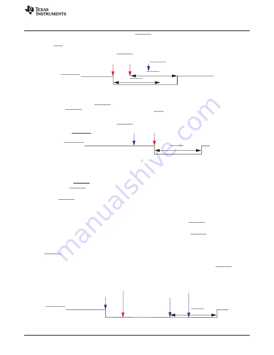
Example 5: The reset of the ERROR pin was requested by the software even before the failure occurs. In
this case, the ERROR pin is set to high immediately after t
ERROR_low
expires. This case is not recommended
and should be avoided by the application.
Figure 16-8. ERROR Pin Timing - Example 5
16.2.3 Forcing an Error Condition
The error response generation mechanism is testable by software by forcing an error condition. This
allows testing the ERROR pin functionality. By writing a dedicated key to the error forcing key register
(ESMEKR), the ERROR pin is set to low for the specified time. The following steps describe how to force
an error condition:
1. Check ERROR Pin Status Register (ESMEPSR). This register must be 1 to switch into the error forcing
mode.
The ESM module cannot be switched into the error forcing mode if a failure has already been detected
in functional mode. The application command to switch to error forcing mode is ignored.
2. Write “1010b” to the error forcing key register (ESMEKR). After that, the ERROR pin should output low
(error force mode).
Once the application puts the ESM module in the error forcing mode, the ERROR pin cannot indicate
the normal error functionality. If a failure occurs during this time, it gets still latched and the LTC is
reset and stopped. The error output pin is already driven low on account of the error forcing mode.
When the ESM is forced back to normal functional mode, the LTC becomes active and forces the
ERROR pin low until the expiration of the LTC (see
).
3. Write “0000” to the error forcing key register (ESMEKR) back to the active normal mode.
If there are no errors detected while the ESM module is in the error forcing mode, the ERROR pin
goes high immediately after exiting the error forcing mode.
Figure 16-9. ERROR Pin Timing - Example 6


