


Producing exact contour transitions
The continuous path mode (G64) is used. This means, that contour transitions such as corners,
chamfers or radii may not be machined precisely.
If you wish to avoid this, there are two different options when programming. Use the additional
programs or program the special feedrate for the transition element.
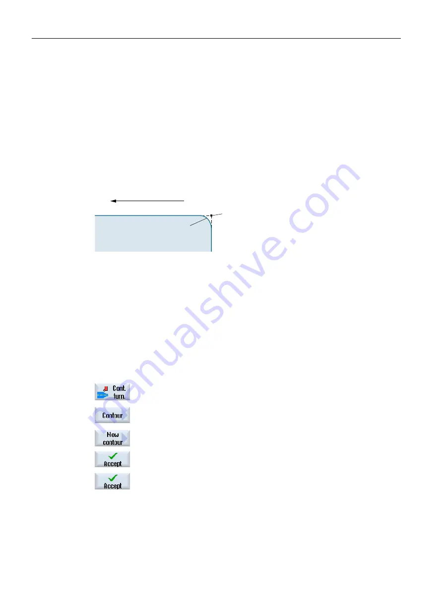
● Additional command
For a contour, first program the vertical straight line and then enter "G9" (non-modal exact
stop) for the additional command parameter. Then program the horizontal straight line. The
corner will be machined exactly, since the feedrate at the end of the vertical straight line is
briefly zero.
0DFKLQLQJGLUHFWLRQ
:RUNSLHFH
*
*
● Feedrate, transition element
If you have chosen a chamfer or a radius as the transition element, enter a reduced feedrate
in the "FRC" parameter. The slower machining rate means that the transition element is
machined more accurately.
Procedure for entering contour elements
1.
The part program is opened. Position the cursor at the required input
position, this is generally at the physical end of the program after M02 or
M30.
2.
Contour input using contour support:
2.1
Press the "Contour turning", "Contour" and "New contour" softkeys.
2.2
In the opened input window, enter a name for the contour, e.g. contour_1.
Press the "Accept" softkey.
2.3
The input screen to enter the contour opens, in which you initially enter
a starting point for the contour. This is marked in the lefthand navigation
bar using the "+" symbol.
Press the "Accept" softkey.
3.
Enter the individual contour elements of the machining direction.
Select a contour element via softkey.
Programming technological functions (cycles)
10.5 Contour turning - Milling/turning machine
Milling
580
Operating Manual, 08/2018, 6FC5398-7CP41-0BA0
Содержание SINUMERIK 828D Turning
Страница 68: ...Introduction 2 4 User interface Milling 68 Operating Manual 08 2018 6FC5398 7CP41 0BA0 ...
Страница 162: ...Setting up the machine 4 12 MDA Milling 162 Operating Manual 08 2018 6FC5398 7CP41 0BA0 ...
Страница 270: ...Machining the workpiece 6 17 Setting for automatic mode Milling 270 Operating Manual 08 2018 6FC5398 7CP41 0BA0 ...
Страница 278: ...Swivel combination 45 90 Simulating machining 7 1 Overview Milling 278 Operating Manual 08 2018 6FC5398 7CP41 0BA0 ...
Страница 294: ...Simulating machining 7 9 Displaying simulation alarms Milling 294 Operating Manual 08 2018 6FC5398 7CP41 0BA0 ...
Страница 316: ...Generating a G code program 8 10 Measuring cycle support Milling 316 Operating Manual 08 2018 6FC5398 7CP41 0BA0 ...
Страница 684: ...Collision avoidance 12 2 Set collision avoidance Milling 684 Operating Manual 08 2018 6FC5398 7CP41 0BA0 ...
Страница 746: ...Tool management 13 16 Working with Multitool Milling 746 Operating Manual 08 2018 6FC5398 7CP41 0BA0 ...
Страница 830: ...Alarm error and system messages 15 9 Remote diagnostics Milling 830 Operating Manual 08 2018 6FC5398 7CP41 0BA0 ...
Страница 846: ... Working with Manual Machine 16 7 More complex machining Milling 846 Operating Manual 08 2018 6FC5398 7CP41 0BA0 ...
Страница 870: ...HT 8 840D sl only 18 5 Calibrating the touch panel Milling 870 Operating Manual 08 2018 6FC5398 7CP41 0BA0 ...
Страница 890: ...Easy Message 828D only 20 7 Making settings for Easy Message Milling 890 Operating Manual 08 2018 6FC5398 7CP41 0BA0 ...
Страница 924: ...Edit PLC user program 828D only 23 8 Searching for operands Milling 924 Operating Manual 08 2018 6FC5398 7CP41 0BA0 ...
Страница 925: ...Appendix A A 1 840D sl 828D documentation overview Milling Operating Manual 08 2018 6FC5398 7CP41 0BA0 925 ...


