


The following machine data is representative for all variable types (INT, BOOL, AXIS, CHAR,
STRING): MD18660 $MN_MM_NUM_SYNACT_GUD_REAL[1].
Note
● System variables can be dependent on the channel. When the channel is switched over,
the values from the selected channel are displayed.
You have the option of having the variable displayed for a specific channel, e.g. $R1:CHAN1
and $R1:CHAN2. The values of channel 1 and channel 2 are displayed, irrespective of the
channel you are in.
● For user variables (GUD), it is not necessary to specify whether they are global or channel-
specific GUD. The first element of a GUD array starts with index 0 as for NC variables.
● Use the tooltip to show the OPI notation for NC system variables (except for GUD).
Servo variables
Servo variables can only be selected and displayed at "Diagnostics" → "Trace".
Changing and deleting values
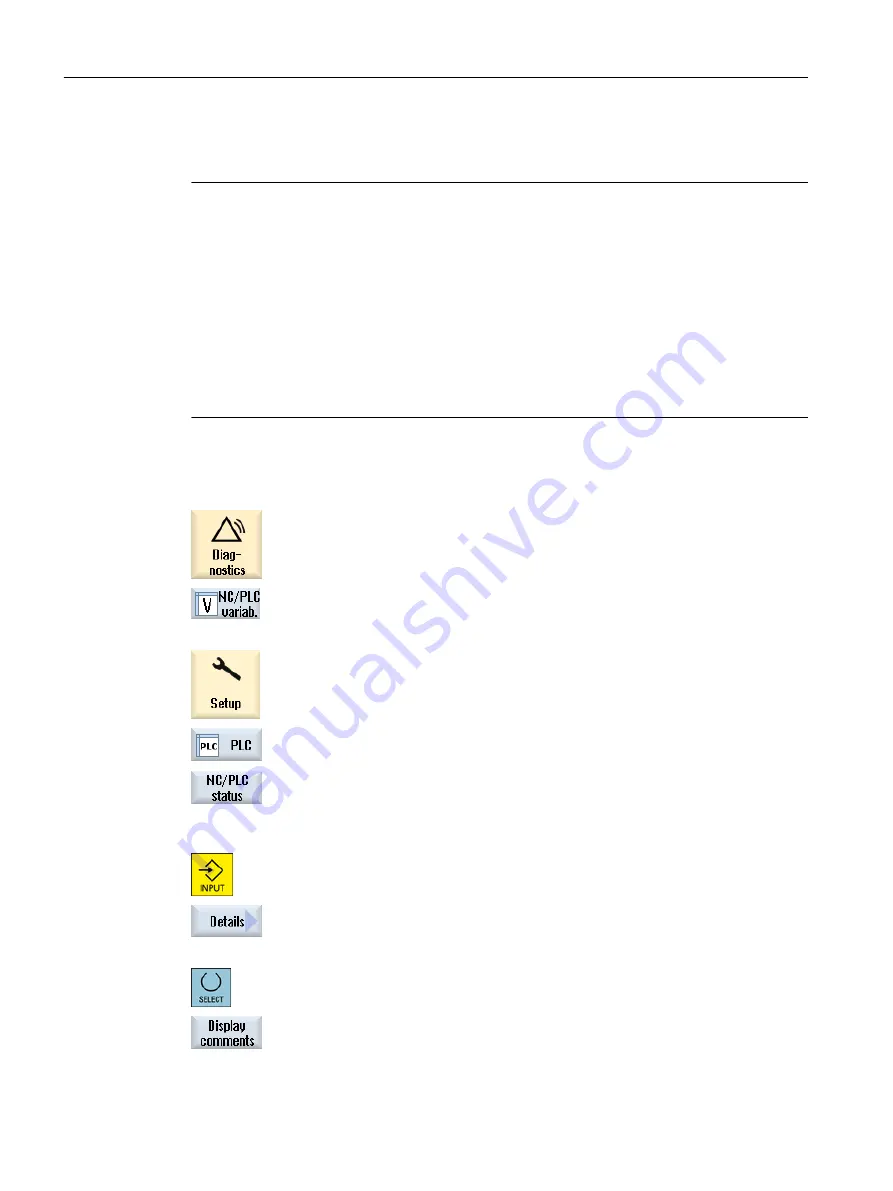
1.
Select the "Diagnostics" operating area.
2.
Press the "NC/PLC variables" softkey.
- OR -
1.
Select the "Startup" operating area.
2.
Press the "PLC" and "NC/PLC variab." softkeys.
The "NC/PLC Variables" window opens.
3.
Position the cursor in the "Variable" column and enter the required vari‐
able.
4.
Press the <INPUT> key.
The operand is displayed with the value.
5.
Press the "Details" softkey.
The "NC/PLC Variables: Details" window opens. The information for "Var‐
iable", "Comment" and "Value" is displayed in full length.
6.
Position the cursor in the "Format" field and select the required format
with <SELECT>.
7.
Press the "Display comments" softkey.
The "Comments" column is displayed. You have the option of creating
comments or editing existing comments.
Edit PLC user program (828D only)
23.3 Displaying and editing PLC and NC variables
Milling
902
Operating Manual, 08/2018, 6FC5398-7CP41-0BA0
Содержание SINUMERIK 828D Turning
Страница 68: ...Introduction 2 4 User interface Milling 68 Operating Manual 08 2018 6FC5398 7CP41 0BA0 ...
Страница 162: ...Setting up the machine 4 12 MDA Milling 162 Operating Manual 08 2018 6FC5398 7CP41 0BA0 ...
Страница 270: ...Machining the workpiece 6 17 Setting for automatic mode Milling 270 Operating Manual 08 2018 6FC5398 7CP41 0BA0 ...
Страница 278: ...Swivel combination 45 90 Simulating machining 7 1 Overview Milling 278 Operating Manual 08 2018 6FC5398 7CP41 0BA0 ...
Страница 294: ...Simulating machining 7 9 Displaying simulation alarms Milling 294 Operating Manual 08 2018 6FC5398 7CP41 0BA0 ...
Страница 316: ...Generating a G code program 8 10 Measuring cycle support Milling 316 Operating Manual 08 2018 6FC5398 7CP41 0BA0 ...
Страница 684: ...Collision avoidance 12 2 Set collision avoidance Milling 684 Operating Manual 08 2018 6FC5398 7CP41 0BA0 ...
Страница 746: ...Tool management 13 16 Working with Multitool Milling 746 Operating Manual 08 2018 6FC5398 7CP41 0BA0 ...
Страница 830: ...Alarm error and system messages 15 9 Remote diagnostics Milling 830 Operating Manual 08 2018 6FC5398 7CP41 0BA0 ...
Страница 846: ... Working with Manual Machine 16 7 More complex machining Milling 846 Operating Manual 08 2018 6FC5398 7CP41 0BA0 ...
Страница 870: ...HT 8 840D sl only 18 5 Calibrating the touch panel Milling 870 Operating Manual 08 2018 6FC5398 7CP41 0BA0 ...
Страница 890: ...Easy Message 828D only 20 7 Making settings for Easy Message Milling 890 Operating Manual 08 2018 6FC5398 7CP41 0BA0 ...
Страница 924: ...Edit PLC user program 828D only 23 8 Searching for operands Milling 924 Operating Manual 08 2018 6FC5398 7CP41 0BA0 ...
Страница 925: ...Appendix A A 1 840D sl 828D documentation overview Milling Operating Manual 08 2018 6FC5398 7CP41 0BA0 925 ...


