


Parameter
Description
Unit
Direction in front
of the contour
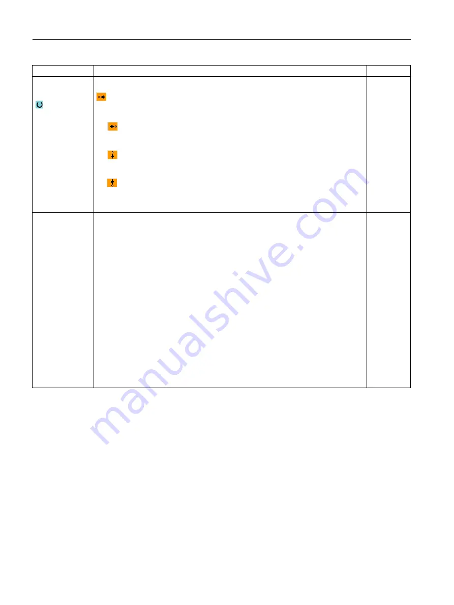
Direction of the contour element towards the starting point:
● In the negative direction of the horizontal axis
● In the positive direction of the horizontal axis
● In the negative direction of the vertical axis
● In the positive direction of the vertical axis
Additional com‐
mands
You can enter additional commands in the form of G code for each contour element. You
can enter the additional commands (max. 40 characters) in the extended parameter
screens ("All parameters" softkey). The softkey is always available at the starting point,
it only has to be pressed when entering additional contour elements.
You can program feedrates and M commands, for example, using additional G code
commands. However, carefully ensure that the additional commands do not collide with
the generated G code of the contour and are compatible with the machining type required.
Therefore, do not use any G code commands of group 1 (G0, G1, G2, G3), no coordinates
in the plane and no G code commands that have to be programmed in a separate block.
The contour is finished in continuous-path mode (G64). As a result, contour transitions
such as corners, chamfers or radii may not be machined precisely.
If you wish to avoid this, then it is possible to use additional commands when programming.
Example:
For a contour, first program the straight X parallel and then enter "G9" (non-modal exact
stop) for the additional command parameter. Then program the Z-parallel straight line.
The corner will be machined exactly, as the feedrate at the end of the X-parallel straight
line is briefly zero.
Note:
The additional commands are only effective for finishing!
10.5.4
Creating contour elements
Creating contour elements
After you have created a new contour and specified the starting point, you can define the
individual elements that make up the contour.
The following contour elements are available for the definition of a contour:
● Straight vertical line
● Straight horizontal line
Programming technological functions (cycles)
10.5 Contour turning - Milling/turning machine
Milling
578
Operating Manual, 08/2018, 6FC5398-7CP41-0BA0
Содержание SINUMERIK 828D Turning
Страница 68: ...Introduction 2 4 User interface Milling 68 Operating Manual 08 2018 6FC5398 7CP41 0BA0 ...
Страница 162: ...Setting up the machine 4 12 MDA Milling 162 Operating Manual 08 2018 6FC5398 7CP41 0BA0 ...
Страница 270: ...Machining the workpiece 6 17 Setting for automatic mode Milling 270 Operating Manual 08 2018 6FC5398 7CP41 0BA0 ...
Страница 278: ...Swivel combination 45 90 Simulating machining 7 1 Overview Milling 278 Operating Manual 08 2018 6FC5398 7CP41 0BA0 ...
Страница 294: ...Simulating machining 7 9 Displaying simulation alarms Milling 294 Operating Manual 08 2018 6FC5398 7CP41 0BA0 ...
Страница 316: ...Generating a G code program 8 10 Measuring cycle support Milling 316 Operating Manual 08 2018 6FC5398 7CP41 0BA0 ...
Страница 684: ...Collision avoidance 12 2 Set collision avoidance Milling 684 Operating Manual 08 2018 6FC5398 7CP41 0BA0 ...
Страница 746: ...Tool management 13 16 Working with Multitool Milling 746 Operating Manual 08 2018 6FC5398 7CP41 0BA0 ...
Страница 830: ...Alarm error and system messages 15 9 Remote diagnostics Milling 830 Operating Manual 08 2018 6FC5398 7CP41 0BA0 ...
Страница 846: ... Working with Manual Machine 16 7 More complex machining Milling 846 Operating Manual 08 2018 6FC5398 7CP41 0BA0 ...
Страница 870: ...HT 8 840D sl only 18 5 Calibrating the touch panel Milling 870 Operating Manual 08 2018 6FC5398 7CP41 0BA0 ...
Страница 890: ...Easy Message 828D only 20 7 Making settings for Easy Message Milling 890 Operating Manual 08 2018 6FC5398 7CP41 0BA0 ...
Страница 924: ...Edit PLC user program 828D only 23 8 Searching for operands Milling 924 Operating Manual 08 2018 6FC5398 7CP41 0BA0 ...
Страница 925: ...Appendix A A 1 840D sl 828D documentation overview Milling Operating Manual 08 2018 6FC5398 7CP41 0BA0 925 ...


