


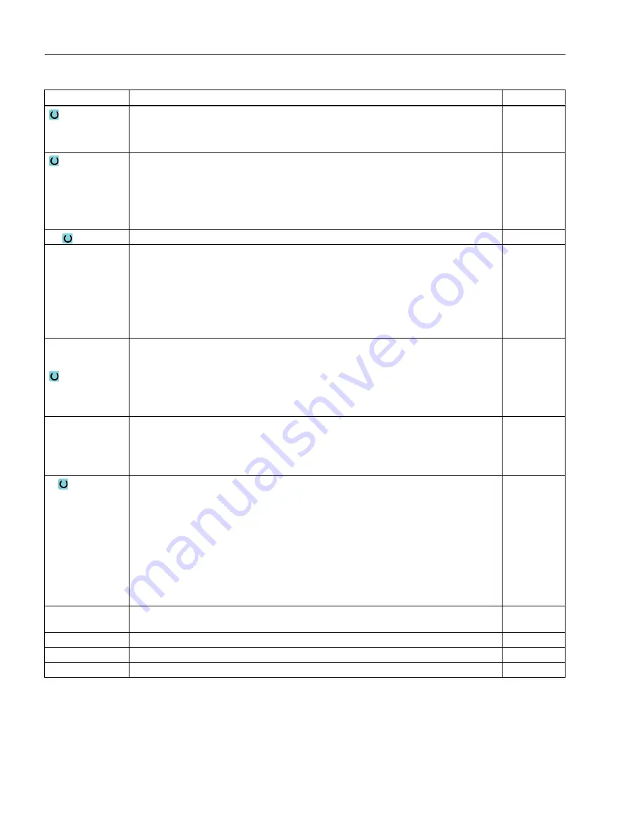
Parameter
Description
Unit
(only for G code)
Machining position:
● Single position
● Position pattern (MCALL)
X0
Y0
Z0
(only for G code)
The positions refer to the center point:
Reference point X – (for single position only)
Reference point Y – (for single position only)
Reference point Z
mm
mm
mm
Z1
End point of the thread (abs) or thread length (inc)
mm
Table
Thread table selection:
● Without
● ISO metric
● Whitworth BSW
● Whitworth BSP
● UNC
Selection – (not
for table "without")
Selection of table value: e.g.
● M3; M10; etc. (ISO metric)
● W3/4"; etc. (Whitworth BSW)
● G3/4"; etc. (Whitworth BSP)
● N1" - 8 UNC; etc. (UNC)
P
Display of the thread pitch for the parameter input in the input field "Table" and "Selection". MODULUS
Turns/"
mm/rev
inch/rev
P
- (selection
option only for ta‐
ble selection "with‐
out")
Pitch ...
● in MODULUS: For instance, used for worms that mesh with a gearwheel.
● per inch: Used with pipe threads, for example.
When entered per inch, enter the integer number in front of the decimal point in the
first parameter field and the figures after the decimal point as a fraction in the second
and third field.
● in mm/rev
● in inch/rev
The tool used depends on the thread pitch.
MODUL
Turns/"
mm/rev
in/rev
∅
Nominal diameter
Example: Nominal diameter of M12 = 12 mm
mm
H1
Thread depth
mm
αS
Starting angle
Degrees
rev
Finishing allowance in X and Y - (only for ∇)
mm
* Unit of feedrate as programmed before the cycle call
Programming technological functions (cycles)
10.2 Milling
Milling
474
Operating Manual, 08/2018, 6FC5398-7CP41-0BA0
Содержание SINUMERIK 828D Turning
Страница 68: ...Introduction 2 4 User interface Milling 68 Operating Manual 08 2018 6FC5398 7CP41 0BA0 ...
Страница 162: ...Setting up the machine 4 12 MDA Milling 162 Operating Manual 08 2018 6FC5398 7CP41 0BA0 ...
Страница 270: ...Machining the workpiece 6 17 Setting for automatic mode Milling 270 Operating Manual 08 2018 6FC5398 7CP41 0BA0 ...
Страница 278: ...Swivel combination 45 90 Simulating machining 7 1 Overview Milling 278 Operating Manual 08 2018 6FC5398 7CP41 0BA0 ...
Страница 294: ...Simulating machining 7 9 Displaying simulation alarms Milling 294 Operating Manual 08 2018 6FC5398 7CP41 0BA0 ...
Страница 316: ...Generating a G code program 8 10 Measuring cycle support Milling 316 Operating Manual 08 2018 6FC5398 7CP41 0BA0 ...
Страница 684: ...Collision avoidance 12 2 Set collision avoidance Milling 684 Operating Manual 08 2018 6FC5398 7CP41 0BA0 ...
Страница 746: ...Tool management 13 16 Working with Multitool Milling 746 Operating Manual 08 2018 6FC5398 7CP41 0BA0 ...
Страница 830: ...Alarm error and system messages 15 9 Remote diagnostics Milling 830 Operating Manual 08 2018 6FC5398 7CP41 0BA0 ...
Страница 846: ... Working with Manual Machine 16 7 More complex machining Milling 846 Operating Manual 08 2018 6FC5398 7CP41 0BA0 ...
Страница 870: ...HT 8 840D sl only 18 5 Calibrating the touch panel Milling 870 Operating Manual 08 2018 6FC5398 7CP41 0BA0 ...
Страница 890: ...Easy Message 828D only 20 7 Making settings for Easy Message Milling 890 Operating Manual 08 2018 6FC5398 7CP41 0BA0 ...
Страница 924: ...Edit PLC user program 828D only 23 8 Searching for operands Milling 924 Operating Manual 08 2018 6FC5398 7CP41 0BA0 ...
Страница 925: ...Appendix A A 1 840D sl 828D documentation overview Milling Operating Manual 08 2018 6FC5398 7CP41 0BA0 925 ...


