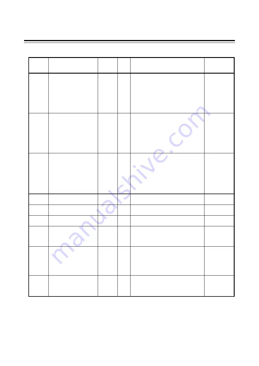
7. COMMUNICATION DATA LIST
IMR01Y36-E2
51
Continued from the previous page.
ID
Name
Number
of data
items
Attri-
bute
Data range
Factory
set value
18
(0x0012)
Output state monitor
64
RO Bit data
Bit 0: The state of OUT1
Bit 1: The state of OUT2
Bit 2: The state of OUT3
Bit 3: The state of OUT4
Bit 4 to Bit 15: Unused
Data
0: OFF
1: ON
[Decimal number: 0 to 15]
⎯
19
(0x0013)
Operation mode state
monitor
64 RO Bit data
Bit 0: Control STOP
Bit 1: Control RUN
Bit 2: Manual mode
Bit 3: Remote mode
Bit 4 to Bit 15: Unused
Data
0: OFF
1: ON
[Decimal number: 0 to 15]
⎯
20
(0x0014)
Memory area soak time
monitor
64 RO 0 minutes 00 seconds to
199 minutes 59 seconds:
0 to 11999 seconds
0 hours 00 minutes to
99 hours 59 minutes:
0 to 5999 minutes
Data range of Area soak time can be
selected on the Soak time unit.
⎯
21
(0x0015)
Integrated operating time
monitor
16
RO 0 to 19999 hours
⎯
22
(0x0016)
Holding peak value ambient
temperature monitor
64 RO
−
10.0 to +100.0
°
C or 14 to 212
°
F
⎯
23
(0x0017)
Unused
⎯
⎯
⎯
⎯
24
(0x0018)
Backup memory state
monitor
64 RO 0: The content of the backup memory does
not coincide with that of the RAM.
1: The content of the backup memory
coincides with that of the RAM.
⎯
25
(0x0019)
Unused
⎯
⎯
⎯
⎯
•
•
•
32
(0x0020)
33
(0x0021)
PID/AT transfer
1, 2
64
R/W 0: PID control
1: Autotuning (AT) *
* Automatically reverts to 0 after
autotuning ends.
0
1
When used in Polling I/O communication, set “PID/AT transfer by Polling I/O communication” in the action mode
selections (ID: 246) to “1: Validate.”
2
When PID/AT transfer is set to “1: Autotuning (AT)” in Polling I/O communication, do not change any of the other
communication data for controllers with AT set until AT ends, as “1: Autotuning (AT)” may set again when AT
ends.
Continued on the next page.


