P/N 016-5030-020 Rev. D
65
VIPER PRO CALIBRATION AND OPERATION
SmarTrax MD system unless a technician instructs you to modify the settings. Pressing Modify PWM Settings
displays the PWM Setup screen to allow manual adjustments to the PWM values.
◦
Auto or Manual
- Toggles between automatic and manual control of the PWM values. If “Manual” is
displayed in the icon, the system is in manual mode and is no longer learning the PWM minimum values.
Pressing the button will switch SmarTrax MD to automatic mode. If “Auto” is displayed, the system is in
automatic mode and is learning the PWM minimum values. Adjusting a PWM Minimum value will switch
SmarTrax MD to manual mode. Raven Industries does not advise leaving the system in auto mode is the
PWM minimum values may change unpredictably.
◦
Left and Right Manual Steer
- Used to manually test the SmarTrax MD system. Select one of the values
or the Min or Max button to steer the machine. If it does not respond as expected, the PWM values may
need to be adjusted.
◦
Target Current
- Displays the expected current level for the mechanical drive to turn the steering wheel.
◦
Actual Current
- Displays the amount of current the system is using to steer the machine.
◦
Exit
- Returns to the System Diagnostic screen.
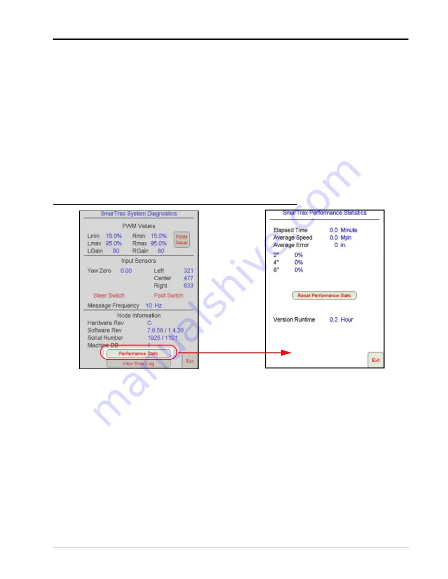
FIGURE 38. System Diagnostics and SmarTrax MD Performance Statistics Screens
•
Performance Stats
- Displays the SmarTrax MD system performance statistics.
◦
Elapsed Time
- Length of time the SmarTrax MD system has been running.
◦
Average Speed
- Average vehicle speed over the last hour while SmarTrax MD has been running.
◦
Average Error
- Average distance from the desired guidance path or line during the last hour while
SmarTrax MD has been running.
◦
1”, 2”, and 4”
- The percentage of time the machine has been within the distance of the guide line during
the last hour. Press Reset Performance Stats to set the fields to zero.
NOTE:
The error percentages are always displayed in inches, regardless of the Display Unit selection. The
equivalent metric values are 5 cm, 10 cm, and 20 cm. On non-RTK systems, the values are 2”, 4”, and
8”.
◦
Version Runtime
- The runtime of the current SmarTrax node software version.
◦
Exit
- Returns to the System Diagnostics screen.
NEED NEW
PERFORMANCE
STATISTICS
SCREEN?
Содержание SmarTrax MD
Страница 6: ...Table of Contents iv SmarTrax MD Calibration Operation Manual ...
Страница 10: ...CHAPTER 1 4 SmarTrax MD Calibration Operation Manual ...
Страница 14: ...CHAPTER 2 8 SmarTrax MD Calibration Operation Manual ...
Страница 46: ...CHAPTER 3 40 SmarTrax MD Calibration Operation Manual ...
Страница 76: ...CHAPTER 4 70 SmarTrax MD Calibration Operation Manual ...
Страница 112: ...CHAPTER 6 106 SmarTrax MD Calibration Operation Manual ...
Страница 114: ...CHAPTER 7 108 SmarTrax MD Calibration Operation Manual FIGURE 1 Cruizer II with Phoenix 300 and Slingshot Steering Only ...
Страница 115: ...7 P N 016 5030 020 Rev D 109 SYSTEM DIAGRAMS FIGURE 2 Envizio Pro or Viper Pro with Slingshot Steering Only ...
Страница 116: ...CHAPTER 7 110 SmarTrax MD Calibration Operation Manual ...
Страница 131: ...P N 016 5030 020 Rev D 125 ROADWAY HOMOLOGATION CERTIFICATION ...
Страница 132: ...CHAPTER 8 126 SmarTrax MD Calibration Operation Manual ...


