SECTION 09: PROPELLER SHAFT
10
DOB 2490-2789 | X3-45 Commuter PA1605 Maintenance Manual (Final Version – Rev.2 April 2016)
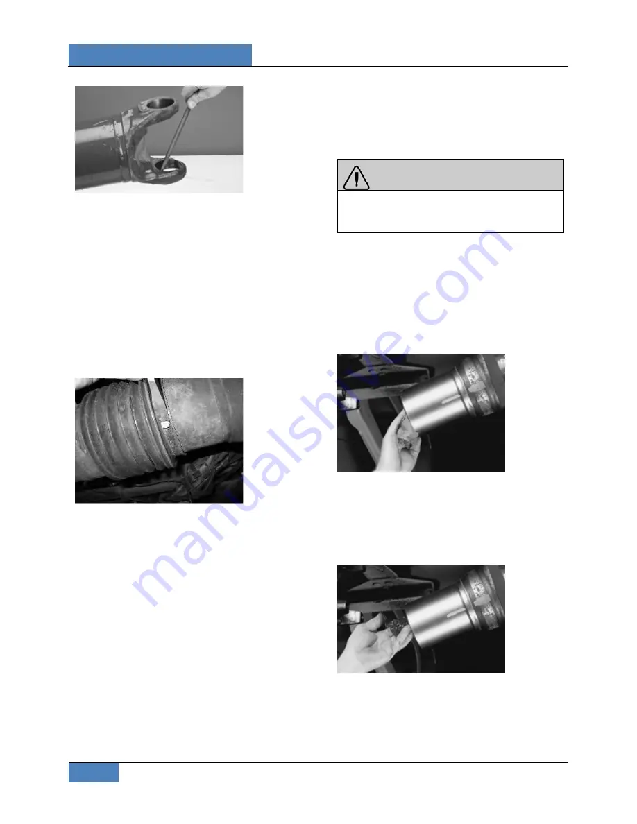
FIGURE 20: RAISED METAL OR FRETTING CAN BE
REMOVED FROM YOKE CROSS HOLES WITH A FINE-
TOOTHED FILE
4.3
REMOVAL PROCEDURE FOR SLIP
MEMBER BOOT
1. It is imperative to mark all mating
components of the propeller shaft. Mark the
propeller shaft with a marking stick, paint
marker or other legible marking device.
2. Remove and discard both boot clamps.
Clamps may be separated using a chisel to
disengage locking hooks. DO NOT reuse
clamps.
FIGURE 21: BOOT CLAMP
3. Completely collapse the boot toward the
yoke shaft to expose weld ring and spline
sleeve area. Wipe weld ring and spline
sleeve areas clean.
4. Remove the yoke shaft and boot from the
spline sleeve. Discard boot.
5. Inspect the yoke shaft spline surface for
damage. If the splines are damaged,
missing or twisted, or any Glidecote is
missing, complete propeller shaft
replacement is necessary.
6. Inspect the spline sleeve for damage. If the
splines are damaged, missing or twisted,
complete propeller shaft replacement is
necessary.
7. Inspect the entire slip assembly for
contaminants. If the slip assembly shows
evidence of rust or the lube is severely
contaminated, complete propeller shaft
replacement is necessary.
5. INSTALLATION
WARNING
Read “Spicer Life Series Driveshaft Installation
Warnings and Cautions” in
Spicer
Driveshaft’s Service Manual DSSM-0100.
5.1
SLIP MEMBER AND BOOT
INSTALLATION
1. Clean ALL grease from yoke shaft and
spline sleeve. Make sure grease-cutting
solvent does not intrude into the tube
through the vent hole in the spline sleeve
plug. Be sure the phasing marks made
during disassembly are not removed.
FIGURE 22: CLEAN GREASE FROM SPLINE SLEEVE
2. After all traces of grease and cutting solvent
have been removed from the yoke shaft and
spline sleeve, apply half of the grease
provided to the yoke shaft splines and the
other half to the spline sleeve, cover the
entire splined surface.
FIGURE 23: APPLY GREASE
3. Measure and place a mark 2.25 inches (55-
60mm) from yoke shaft shoulder with a
marking stick, paint marker or other legible
marking device.
Содержание X3-45 COMMUTER
Страница 4: ......
Страница 20: ......
Страница 50: ......
Страница 82: ......
Страница 198: ......
Страница 202: ......
Страница 212: ......
Страница 232: ......
Страница 270: ......
Страница 304: ......
Страница 322: ......
Страница 351: ...SECTION 16 SUSPENSION DOB 2490 2789 X3 45 Commuter PA1605 Maintenance Manual Section 16 revised April 2019 9...
Страница 352: ...SECTION 16 SUSPENSION 10 DOB 2490 2789 X3 45 Commuter PA1605 Maintenance Manual Section 16 revised April 2019...
Страница 370: ......
Страница 474: ......
Страница 542: ......


