SECTION 07: TRANSMISSION
DOB 2490-2789 | X3-45 Commuter PA1605 Maintenance Manual (Final Version – Rev.2 April 2016)
11
system as per Section 05
‘’Cooling’’
, paragraph
7: Flushing
.
1. Remove the rear L.H. side tag axle wheel,
then remove the rear L.H. side fender panel.
2. Disconnect the two transmission hoses from
oil cooler. Cover hose ends and fittings to
prevent fluid contamination (Figure 7).
WARNING
A significant amount of oil may drain from oil
lines when they are disconnected.
3. Unfasten the constant-torque hose clamps
and remove the two hoses.
4. Unscrew the four holding nuts and remove
the U-bolts, remove the oil cooler from
engine compartment.
5. Reinstall transmission oil cooler by using
reverse procedure.
4.2
TRANSMISSION WITH RETARDER
Stop engine and allow engine to cool. Close
both heater line shutoff valves (refer to Section
05
‘’Cooling’’
).
1. To drain the cooling system, proceed as per
Section 05
‘’Cooling’’
, paragraph 5: Draining.
If the cooling system is contaminated, flush
system as per Section 05
‘’Cooling’’
,
paragraph 7: Flushing
.
2. Remove the rear L.H. side tag axle wheel,
then remove the rear L.H. side fender panel.
3. Disconnect the transmission hoses from oil
cooler. Cover hose ends and fittings to
prevent fluid contamination.
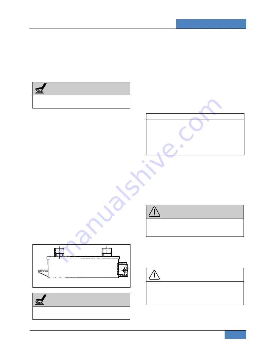
FIGURE 7: COOLER WITH RETARDER
07073
WARNING
A significant amount of oil may drain from oil
lines when they are disconnected.
4. Unfasten the constant-torque hose clamps
and remove the two hoses.
5. Unscrew the holding bolts and nuts and
remove the oil cooler from engine
compartment.
5. ALLISON TRANSMISSION INSTALLATION
1. Place the transmission on a transmission
jack.
2. Install a headless guide bolt into one of the
12 threaded holes for flexible plate attaching
screws in the flywheel.
NOTE
For more clearance between the tag axle and
transmission, the tag axle may be unloaded
and jacked up, or retracted (if applicable).
With the starter motor removed, align one of
the 12 attaching screw holes in the flexible
plate with the access opening.
3. Lubricate the flywheel center pilot boss with
molybdenum disulfide grease (Molycote G, or
equivalent).
4. Raise transmission and position the flywheel
pilot boss into the flexible plate adapter. Align
the guide bolt previously installed in the
flywheel with the flexible plate hole facing the
access opening in the flywheel housing.
WARNING
Severe damages and/or personal injury can
occur if transmission is not adequately
supported.
5. Seat the transmission against the engine
flywheel housing. NO FORCE IS
REQUIRED. If interference is encountered,
move the transmission away from engine,
then investigate the cause.
CAUTION
The torque converter housing must be seated
against the flywheel housing prior to tightening
any screws. DO NOT USE SCREWS TO
SEAT THE HOUSING.
6. Start all torque converter housing screws,
and then tighten four of them gradually and in
a criss-cross sequence around the housing.
Tighten the 12 remaining screws.
Содержание X3-45 COMMUTER
Страница 4: ......
Страница 20: ......
Страница 50: ......
Страница 82: ......
Страница 198: ......
Страница 202: ......
Страница 212: ......
Страница 232: ......
Страница 270: ......
Страница 304: ......
Страница 322: ......
Страница 351: ...SECTION 16 SUSPENSION DOB 2490 2789 X3 45 Commuter PA1605 Maintenance Manual Section 16 revised April 2019 9...
Страница 352: ...SECTION 16 SUSPENSION 10 DOB 2490 2789 X3 45 Commuter PA1605 Maintenance Manual Section 16 revised April 2019...
Страница 370: ......
Страница 474: ......
Страница 542: ......


