


Appendix C
Hardware and Software Configuration
© National Instruments Corp.
C-5
GPIB-410 User Manual
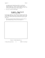
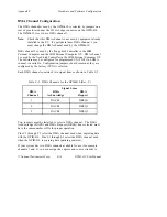
DMA Channel Configuration
The DMA channel used by the GPIB-410 is selected by jumpers on two
rows of pins located near the I/O slot edge connector on the GPIB-410
(W1 and W2 in Figure C-1). The GPIB-410 is set to use DMA channel
1.
Note:
Check that this DMA channel is not used by equipment already
installed in the PC. If a peripheral uses DMA channel 1, you
must change the DMA channel used by the GPIB-410.
DMA channel 2 is used by the floppy disk Controller in the IBM
Personal Computer and the IBM Personal Computer XT. DMA channel
3 is used by the fixed disk Controller in the IBM Personal Computer XT.
The software can be configured for programmed I/O (PIO) if no DMA
channel is available. Configuration jumpers should remain as they are
configured by the factory if PIO is selected.
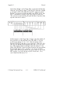
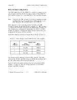
Each DMA channel consists of two signal lines as shown in Table C-1:
Table C-1. DMA Channels for the GPIB-410 (Rev. B.2 or Higher)
Signal Lines
DMA
DMA
DMA
Channel
Acknowledge
Request
1
DACK1
DREQ1
2
DACK2
DREQ2
3
DACK3
DREQ3
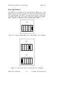
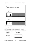
Two jumpers must be installed to select a DMA channel. The DMA
Acknowledge (DACK) and DMA Request (DREQ) lines selected must
have the same number suffix for proper operation.
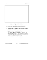
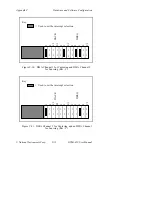
Figure C-3 shows the jumper placement for the factory default DMA
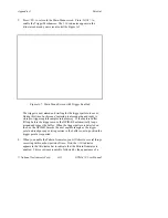
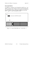
channel 1. Figure C-4 shows the jumper placement to select DMA
channel 2 and DMA channel 3.


