


Chapter 3
Overview
© National Instruments Corp.
3-3
GPIB-410 User Manual
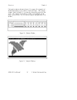
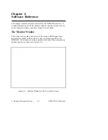
The Monitor Window
The monitor window graphically displays the current state of the GPIB
through simulated LED indicators. Each LED has a corresponding
toggle switch through which you can assert the associated signal on the
bus. In addition, the status of the eight bus data lines is indicated in
both character and hexadecimal formats.
Figure 3-4. GPIB Status Indicators
The following list shows how the LEDs and switches appear when they
are on and off.
Switch (on)
Switch (off)
LED (on)
LED (off)
As shown in Figure 3-4, the top half of the monitor window displays the
current value of each signal on the GPIB. If the GPIB signal is asserted,
the LED is on. If the GPIB signal is not asserted, the LED is off. The
bottom half of the monitor window displays the current user switch
selection for asserting or unasserting GPIB signals. If the switch is on
(or up), the GPIB-410 is currently asserting that signal on the GPIB.


