


Hardware and Software Configuration
Appendix C
GPIB-410 User Manual
C-14
© National Instruments Corp.
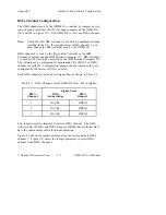
separate channels for simultaneous DMA operation of both. However, if
your system has only one available channel, both jumpers must be set to
that channel for DMA operation of capturing or sourcing, but not both at
the same time.
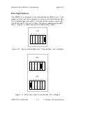
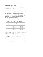
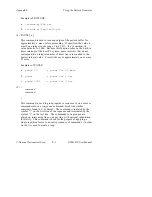
Figure C-9 shows DMA channel 1 selected for both capturing and
sourcing (that is, input and output). Notice that with this configuration,
DMA may not be used by the capture circuitry and pattern generator at
the same time. This is the factory default configuration. Figure C-10
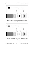
shows DMA channel 1 selected for capturing and DMA channel 3
selected for sourcing. Figure
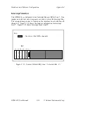
C-11 shows DMA channel 1 selected for capturing with no DMA
channel selected for sourcing. Programmed I/O must be used in this
case.
1
2
C3
S1
2
3
S1
2
3
1
2
C3
DREQ
DACK
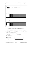
Key:
= Used to set the interrupt selection
•
•
•
•
•
•
•
•
•
•
•
•
•
•
•
•
Figure C-9. Factory Default DMA Channel 1 (Rev. C)


