background image

193

3. FUNCTION

3.14 Firmware update

1

2

3

4

5

6

7

8

9

10

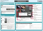
Selecting interface

Select Ethernet Adapter window

Select the network adapter to which the personal computer and inverter are connected.

Scan Network window

• The inverters connected to the personal computer are detected in the IP address range specified in the "Scan Network"

window.

• The inverter reset time and communication check time interval after firmware update can be set.

NOTE

• To update the firmware of inverters having addresses in different networks, set the default gateway address of the personal

computer and 

Pr.442 to Pr.445 Default gateway address

 of the FR-E800 inverters.

• To search the inverters in different networks, configure networks using a router. Up to 512 inverters can be searched.

Symbol

Name

Function/description

A

USB

Detects the inverters connected to the personal computer using the USB connector. This 
interface is initially selected.

B

Ethernet

Detects the inverters connected to the personal computer using the Ethernet connector.

C

Select adapter

Enabled when Ethernet is selected. "Select Ethernet Adapter" window appears.

D

Scan network

Enabled when Ethernet is selected. "Scan Network" window appears.

E

Network information

Enabled when Ethernet is selected. Shows the settings set in "Select Ethernet Adapter" and 
"Scan Network" windows.

Symbol

Name

Function/description

A

Select Ethernet Adapter Only the adapters connected to the network are displayed.

Symbol

Name

Function/description

A

Search address

• Search for VFDs in the same network

The inverters are searched in the IP address range of the personal computer.

• Search for VFDs in different networks

The inverters are searched in the specified IP address range.

B

Time  setting

• Waittime for VFD reset

Set the delay time from when the firmware update is complete until inverter reset
is performed.

• Timeout

Set the communication check time interval for communication with the inverters.

A

E

B

C

D

A

A

B

Содержание MELSOFT FR Configurator2

Страница 1: ...FR Configurator2 INSTRUCTION MANUAL INVERTER FR Configurator2 SW1DND FRC2 E INSTRUCTION MANUAL X SW1DND FRC2 E INVERTER SETUP SOFTWARE IB NA 0600516ENG X 2112 MEE Specifications subject to change without notice ...

Страница 2: ... Connection of multiple inverters using RS 485 terminals 48 1 4 8 Connection through GOT FA transparent function 51 1 4 9 Connection with programmable controller 58 1 4 10 Connection via a GOT2000 model and a programmable controller 58 1 4 11 Connection using CC Link IE TSN 59 1 5 Setting of operation mode of the inverter 65 1 6 Start and close of FR Configurator2 69 1 6 1 Starting FR Configurator...

Страница 3: ...ature 118 3 3 Convert 120 3 3 1 Schematic illustration of the convert function 120 3 3 2 Convert window 121 3 3 3 Connection setting for the convert function 122 3 3 4 Convert procedures 122 3 3 5 Precautions for the convert function 125 3 4 Graph 134 3 4 1 Graph window 135 3 4 2 Graph window toolbar 135 3 4 3 Sampling settings 136 3 4 4 Trigger settings 139 3 4 5 Changing scale and the graph disp...

Страница 4: ...fying parameters 180 3 12 Ethernet parameter setting function 182 3 12 1 Ethernet parameter setting 182 3 12 2 Batch assignment dialog 184 3 12 3 Writing result 185 3 12 4 Procedure for connecting inverters via Ethernet 186 3 13 iQSS backup file conversion function 188 3 13 1 iQSS backup file conversion 188 3 14 Firmware update 189 3 14 1 Applicable inverter 189 3 14 2 Connection and parameter set...

Страница 5: ...d trademark of Fuji Xerox Corporation MODBUS is a registered trademark of SCHNEIDER ELECTRIC USA INC FR Configurator2 is a registered trademark of Mitsubishi Electric Corporation The copyright and other rights of this software all belong to Mitsubishi Electric Corporation No part of this Instruction Manual may be copied or reproduced without the permission of Mitsubishi Electric Corporation Other ...

Страница 6: ...uct was manufactured under conditions of strict quality control you are strongly advised to install safety devices to prevent serious accidents when it is used in facilities where breakdowns of the product are likely to cause a serious accident Design precautions To maintain the security confidentiality integrity and availability of the inverter and the system against unauthorized access DoS 1 att...

Страница 7: ...6 MEMO ...

Страница 8: ...OUTLINE 1 1 Before using this software 9 1 2 System configuration 13 1 3 Installation and uninstallation 22 1 4 Connection and parameter setting 26 1 5 Setting of operation mode of the inverter 65 1 6 Start and close of FR Configurator2 69 ...

Страница 9: ...er FR B 700 Mitsubishi Electric FR B inverter A700 specifications FR B3 700 Mitsubishi Electric FR B3 inverter A700 specifications FR D700 Mitsubishi Electric FR D700 series inverter FR F700 Mitsubishi Electric FR F700 series inverter FR F700P Mitsubishi Electric FR F700P series inverter FR E700 Mitsubishi Electric FR E700 series inverter FR E700 NE Mitsubishi Electric FR E700 inverter Ethernet mo...

Страница 10: ...t are determined using AI technology to suggest corrective actions Graph Displays the values monitored by the high speed or monitor sampling and the USB trace file in a graph format Batch Monitor Displays the monitored items of the inverter in a batch I O terminal monitor Displays the I O terminal status in a batch Test operation Test operation allows the selected inverter s frequency to be displa...

Страница 11: ...unction Manual IB 0600813ENG FR A840 LC Liquid Cooled Type Instruction Manual Hardware IB 0600683ENG FR A870 LC Liquid Cooled Type Instruction Manual Hardware IB 0600613ENG FR F800 Instruction Manual Startup IB 0600545 FR F800 Instruction Manual Detailed IB 0600547ENG FR F802 Separated Converter Type Instruction Manual Hardware IB 0600550ENG FR F806 IP55 UL Type 12 Specifications Instruction Manua...

Страница 12: ...on Guideline IB 0600718ENG FR E700EX Instruction Manual Basic IB 0600506ENG FR E700EX Instruction Manual Applied IB 0600507ENG FR D700 G Instruction Manual Basic IB 0600477ENG FR D700 G Instruction Manual Applied IB 0600478ENG GX Works2 Version 1 Operating Manual Common SH 080779ENG Manual name Manual number USB connection c d d Set the operation mode to PU operation mode Type of connection with i...

Страница 13: ...123 PU communication waiting time setting 9999 34 e Set the station number in Pr 331 RS 485 communication station number used for connecting multiple inverters Set Pr 336 RS 485 communication check time interval 0 and Pr 337 RS 485 communication waiting time setting 9999 48 f FR A800 E F800 E E800 SC E Set the station number in Pr 1425 Ethernet communication station number used for connecting mult...

Страница 14: ... Pro Enterprise IoT Enterprise 3 Windows 8 1 4 Windows 7 SP1 or later Professional Enterprise Processor Intel Core i3 or higher or equivalent Memory 4 GB or more Windows 10 Windows 8 1 Windows 7 64 bit Edition 2 GB or more Windows 10 Windows 8 1 Windows 7 32 bit Edition Disk space Free area of 7 GB or more Display Applicable to display at resolution of 1024 768 or more and 256 colors or more Compa...

Страница 15: ...R A842 CRN 07700 315K to 12120 500K Separated converter type FR A820 E CRN 00046 0 4K to 04750 90K Standard model Crane function Ethernet model FR A840 E CRN 00023 0 4K to 06830 280K FR A842 E CRN 07700 315K to 12120 500K Separated converter type FR A820 R2R 00046 0 4K to 04750 90K Standard model Roll to Roll function FR A840 R2R 00023 0 4K to 06830 280K FR A842 R2R 07700 315K to 12120 500K Separa...

Страница 16: ...3 to 12120 0 4K to 500K FR A760 00017 to 06630 FR B A700 series FR B 200V 750 to 3700 5 5K to 75K FR B 400V 750 to 3700 7 5K to 110K FR B3 A700 series FR B3 N 400 to 3700 5 5K to 37K FR B3 N H FR F700 series FR F720 0 75K to 110K 00046 to 04750 FR F740 0 75K to 560K 00023 to 12120 00023 to 12120 S75K to S630K CHT 0 75K to 55K CHT1 FR F700P series FR F720P 0 75K to 110K FR F740P 0 75K to 560K FR E7...

Страница 17: ...oftware For a product details or the newest driver software contact the cable manufacturer 4 Recommended USB cable for computer inverter connection MR J3USBCBL3M cable length 3 m 5 Communication is available via the PU connector RS 485 terminals or USB connector 6 Maximum overall length of connection cable 500 m 7 Select a USB connector or a serial port one of the ports 1 to 63 on the communicatio...

Страница 18: ...hernet connector Ethernet connector Ethernet connector Ethernet connector QCPU LCPU RCPU Programmable controller 2 Ethernet connector 1 GOT2000 Ethernet connector Ethernet connector Ethernet cable Connector Standard Category 5e or higher straight cable double shielded STP RJ 45 connector Use cables compliant with the following standards IEEE 802 3 1000BASE T ANSI TIA EIA 568 B Category 5e Number o...

Страница 19: ...munication USB cable Personal computer FR Configurator2 Inverter USB mini B connector USB connector converter Serial cable Personal computer FR Configurator2 Inverter PU connector RS 232C RS 485 Serial port or USB connector converter USB cable Inverter PU connector USB RS 485 Ethernet cable Personal computer FR Configurator2 Inverter Ethernet connector Ethernet connector RS 232C RS 485 converter S...

Страница 20: ... inverters via a GOT1000 model Ethernet cable Up to 120 inverters Personal computer FR Configurator2 Inverter Ethernet connector Ethernet connector Hub Personal computer FR Configurator2 Ethernet connector Inverter Communication connector CC Link IE TSN communication Up to 120 inverters GOT RS 422 GOT1000 communication unit USB connector Serial port USB serial cable RS 422 Up to 32 inverters can b...

Страница 21: ...ter FR Configurator2 USB cable RS 485 terminal block USB connector Hub Ethernet connector Inverter Inverter Ethernet cable Computer to programmable controller CPU module Ethernet module Up to 120 inverters Personal computer FR Configurator2 Inverter Ethernet connector USB connector Serial port Ethernet connector CC Link IE Field Network Programmable controller CC Link IE Filed Network master modul...

Страница 22: ...dule Ethernet module Programmable controller Ethernet module to inverter Inverter Ethernet connector CC Link IE TSN communication Up to 120 inverters GOT2000 USB connector Serial port USB serial cable Personal computer FR Configurator2 Ethernet connector Ethernet cable Hub GOT to programmable controller CPU module Ethernet module Up to 64 or 120 inverters Inverter Programmable controller Ethernet ...

Страница 23: ...l the software follow the installation procedure in Windows screen In an operation system with antivirus security software a warning may appear when installing FR Configurator2 If a warning appears permit the installation of FR Configurator2 according to the setting procedure of your antivirus security software Installation procedure The following section describes the procedures of installing FR ...

Страница 24: ...folder and click Next To change the installation folder click Change and select an installation folder A new folder FRC2 is created at the selected installation folder This software is installed there If the installation folder is not changed the software is installed at C Program Files MELSOFT FRC2 6 The following window will be displayed Diagnosis data are stored in the computer that contains th...

Страница 25: ...dministrator Administrator account the installation cannot be performed Log in as a user with administrator permission and start the installation again When NET Framework version 3 5 3 0 or 2 0 is disabled the installation is not completed Enable NET Framework version 3 5 3 0 or 2 0 and try the installation again 1 3 2 Uninstallation of FR Configurator2 Open the Start menu of Windows and then clic...

Страница 26: ...running Uninstall the program after closing the application For Windows 8 1 uninstall the software as follows 1 Select Control Panel from the All Apps list and display Uninstall or change a program 2 Select FR Configurator2 and click the Delete button For Windows 10 uninstall the software as follows 1 Right click the Start button to select Apps features and display the setting window Or click Sett...

Страница 27: ...1 1 connection is supported Connection with using USB hub is not supported Serial communication PU connector Refer to page 34 Connect to PU connector of the inverter Serial port RS 485 converter cable or USB RS 485 converter cable is required Ethernet connection Ethernet connector CC Link IE Field Network Basic Refer to page 39 Connection to the Ethernet connector of the inverter Up to 120 inverte...

Страница 28: ...Human Machine Interface connection to the RS 485 terminal block is available For the GOT1000 series an RS 422 communication unit is required For the compatible version of GOT or details of the RS 422 485 connection refer to the GOT1000 GOT2000 Series Connection Manual Personal computer FR Configurator2 Ethernet connector Inverter Communication connector CC Link IE TSN communication Up to 120 inver...

Страница 29: ...mputer to programmable controller CPU module Ethernet module Programmable controller Ethernet module to inverter Up to 64 or 120 inverters Personal computer FR Configurator2 Inverter Ethernet connector USB connector Serial port Ethernet connector Hub Computer to programmable controller CPU module Ethernet module Up to 120 inverters Personal computer FR Configurator2 Inverter Ethernet connector USB...

Страница 30: ...h setting may disable the communication with FR Configurator2 For Pr 999 refer to the Instruction Manual Detailed of the inverter Only the USB connection is available for connecting a GOT2000 model to a personal computer The USB driver must be installed for USB communication with the programmable controller CPU For installing the driver refer to the Operating Manual of GX Works with the version ap...

Страница 31: ...1 connection is supported Connection using USB hub is not supported Model USB Serial communication Serial communication RS 485 terminal block Ethernet Ethernet CC Link IE TSN communication FR A800 FR A800 E FR A800 and FR A8NCG FR B FR B3 FR B4 FR F800 FR F800 E FR F800 and FR A8NCG FR E800 FR E800 EPA FR E800 EPB FR E800 EPC FR E800 SCEPA FR E800 SCEPB FR CS80 FR A700 FR B A700 FR B3 A700 FR F700...

Страница 32: ...able to the USB device mini B connector on the inverter FR E800 series inverter FR A700 FR B 700 and FR B3 700 USB host A connector USB device mini B connector Communication status LED USB cable USB connector USB cable USB connector Place a flathead screwdriver etc in a slot and push up the cover to open Removal of cover ...

Страница 33: ...mini B connector receptacle FR A700 FR B 700 and FR B3 700 USB B connector B receptacle Recommended USB cable MR J3USBCBL3M cable length 3 m Inverter Parameter setting Operation mode Communication parameter Command source parameter FR A800 E FR B FR B3 FR B4 FR F800 E FR E800 E SCE Pr 548 USB communication check time interval 9999 initial value Pr 551 PU mode operation command source selection 3 o...

Страница 34: ...51 2 3 D013 PU mode operation command source selection 9999 1 RS 485 terminals are the command interface enabled in the PU operation mode 2 The PU connector is the command interface enabled in the PU operation mode 3 The USB connector is the command interface enabled in the PU operation mode 5 The Ethernet connector is the command interface enabled in the PU operation mode 9999 USB automatic recog...

Страница 35: ...yed 1 4 4 Connection using PU connector PU connector is used for connecting with a computer Serial port RS 485 converter cable or USB RS 485 converter cable is required PU connector pin layout FR A800 FR F800 series inverter converter Serial cable Personal computer FR Configurator2 Inverter PU connector RS 232C RS 485 Serial port or USB connector converter USB cable Inverter PU connector USB RS 48...

Страница 36: ...er Receptacle side Front view 8 1 to Inverter receptacle Front view 8 1 Inverter receptacle bottom view 8 1 Inverter receptacle Front view 8 1 Pin number Name Description 1 SG Earth ground connected to terminal 5 2 Operation panel power supply 3 RDA Inverter receive 4 SDB Inverter send 5 SDA Inverter send 6 RDB Inverter receive 7 SG Earth ground connected to terminal 5 8 Operation panel power supp...

Страница 37: ...n the following table NOTE Set 9999 in Pr 122 PU communication check time interval Set a station number of each inverter in Pr 117 PU communication station number for multiple connection Perform inverter reset after setting the parameter Product name Remarks 10BASE T cable Cable compliant with EIA 568 such as 10BASE T cable RJ 45 connector Inverter Communication option Parameter setting Operation ...

Страница 38: ... PU communication parity check 2 0 Without parity check 1 With parity check at odd numbers 2 With parity check at even numbers 122 N026 PU communication check time interval 9999 0 PU connector communication is disabled 0 1 to 999 8 s Set the communication check time interval If a no communication state persists for the permissible time or longer the inverter output is shut off The operation depend...

Страница 39: ...is set the communication speed is 19200 bps 119 PU communication stop bit length data length 1 0 Stop bit length 1 bit Data length 8 bits 1 Stop bit length 2 bits 10 Stop bit length 1 bit Data length 7 bits 11 Stop bit length 2 bits 120 PU communication parity check 2 0 Without parity check 1 With parity check at odd numbers 2 With parity check at even numbers 122 PU communication check time inter...

Страница 40: ...rter in Pr 1425 Ethernet communication station number for multiple connection Pr 1432 Ethernet communication check time interval 9999 initial value Pr 550 NET mode operation command source selection 5 initial value 9999 NET Connected Pr 551 PU mode operation command source selection 5 initial value 9999 PU FR A800 E R2R Not connected Set the station number of each inverter in Pr 1074 Ethernet comm...

Страница 41: ...n selection 3 9999 1430 N633 Ethernet function selection 4 9999 1426 N641 Link speed and duplex mode selection 0 0 to 4 Set the communication speed and the communication mode full duplex half duplex 1455 N642 Keepalive time 3600 s 1 to 7200 s When no response is returned for an alive check message Keep Alive ACK for the time s set in Pr 1455 multiplied by 4 elapsed the connection will be forced to...

Страница 42: ...ction via Ethernet In this case operation commands cannot be sent via Ethernet with MODBUS TCP protocol When four or more clients attempt a connection to the inverter during MODBUS TCP protocol communication the connection attempted from outside of the IP address range set for Ethernet command source selection may be forced to be closed 1450 N671 Ethernet command source selection IP address 2 0 0 ...

Страница 43: ...alive check message Keep Alive ACK for the time s set in Pr 1455 multiplied by 4 elapsed the connection will be forced to be closed 1431 N643 Ethernet signal loss detection function selection 0 0 Signal loss detection disabled Set the availability of the signal loss detection and select the action when Ethernet communication is interrupted by physical factors 1 A warning EHR is output for a signal...

Страница 44: ...ide of the IP address range set for Ethernet command source selection may be forced to be closed 1450 N671 Ethernet command source selection IP address 2 0 0 to 255 1451 N672 Ethernet command source selection IP address 3 0 0 to 255 1452 N673 Ethernet command source selection IP address 4 0 0 to 255 1453 N674 Ethernet command source selection IP address 3 range specification 9999 0 to 255 9999 145...

Страница 45: ...etwork In this case operation through the Ethernet network MODBUS TCP or CC Link IE Field Network Basic is not available When four or more clients attempt a connection to the inverter during MODBUS TCP communication the connection attempted from outside of the IP address range set for Ethernet command source selection may be forcibly closed 845 Ethernet command source selection IP address 2 0 0 to...

Страница 46: ...verter belongs can be set in Pr 438 to Pr 441 439 1 2 N711 Subnet mask 2 0 255 3 0 to 255 440 1 2 N712 Subnet mask 3 0 255 3 0 to 255 441 1 2 N713 Subnet mask 4 0 0 to 255 1442 1 2 N760 IP filter address 1 Ethernet 0 0 to 255 Set the range of connectable IP addresses for the network devices When Pr 1442 to Pr 1445 0 initial value the function is invalid 1443 1 2 N761 IP filter address 2 Ethernet 0...

Страница 47: ... to 6 In the torque control mode the torque command source can be selected 810 H700 Torque limit input method selection 0 0 to 2 The torque limit input method can be selected Pr Name Initial value Setting range Description 1320 to 1329 N810 to N819 1 User Defined Cyclic Communication Input 1 to 10 Mapping 9999 5 3 100 3 12288 to 13787 20488 20489 24672 24689 24698 24703 24705 24707 24708 24719 247...

Страница 48: ...ng Pr 1330Pr 1394 upper 8 bits Subindex to which the index number is specified using Pr 1331 1395 1 User Defined Cyclic Communication Output Sub 3 and 4 Mapping 0 0 to 2 256 to 258 512 to 514 Pr 1395 lower 8 bits Subindex to which the index number is specified using Pr 1332Pr 1395 upper 8 bits Subindex to which the index number is specified using Pr 1333 1396 1 User Defined Cyclic Communication Ou...

Страница 49: ...lock Serial port Inverter Communication option Parameter setting Operation mode Communication parameter Command source parameter FR A800 FR B FR B3 FR B4 FR F800 FR A700 FR B 700 FR B3 700 FR F700 FR F700P Not connected Set the station number of each inverter in Pr 331 RS 485 communication station number for multiple connection Pr 336 RS 485 communication check time interval 0 initial value 0 Pr 3...

Страница 50: ...to 31 Set the inverter station number Set the inverter station numbers when two or more inverters are connected to one personal computer 336 N036 RS 485 communication check time interval 0 s 0 RS 485 communication is enabled However the inverter output is shut off if operation is changed to NET operation mode 0 1 to 999 8 s Set the interval of communication check signal loss detection time If a no...

Страница 51: ...r 0 0 to 31 Set the inverter station number Set the inverter station numbers when two or more inverters are connected to one personal computer 336 RS 485 communication check time interval 0 s 0 RS 485 communication is enabled However the inverter output is shut off if operation is changed to NET operation mode 0 1 to 999 8 s Set the interval of communication check signal loss detection time If a n...

Страница 52: ...R Configurator2 is available through a GOT The FA transparent function enables reading writing and monitoring of a programmable controller of Mitsubishi Electric Corporation through a GOT while connecting the Mitsubishi Electric programmable controller and a personal computer A serial port or USB is used for connecting the personal computer and the GOT RS422 485 is used for connecting the GOT and ...

Страница 53: ...tor Serial port USB serial cable RS 422 Up to 32 inverters can be connected RS 485 terminal block Personal computer FR Configurator2 GOT2000 RS 422 485 Up to 32 inverters can be connected Personal computer FR Configurator2 USB cable RS 485 terminal block USB connector PU connector Terminating resistor Station number 1 Station number 2 Station number n GOT1000 RS 422 Distributor GOT RS 422 communic...

Страница 54: ...tting in Pr 999 is required For connecting a GOT2000 model to the RS 485 terminal block on the inverter set Pr 549 Protocol selection 0 initial value or 1 For connection to a device other than the GOT2000 series initial setting in Pr 999 is required For details refer to the GOT2000 Series Connection Manual Mitsubishi Product Related parameters for connection through GOT Set communication related p...

Страница 55: ...o the inverter and response 9999 Set with communication data 124 N028 PU communication CR LF selection 1 0 Without CR LF 1 With CR 2 With CR LF 331 N030 RS 485 communication station number 0 0 to 31 0 to 247 Sets the inverter station number Same specifications as Pr 117 332 N031 RS 485 communication speed 96 3 6 12 24 48 96 192 384 576 768 1152 Select the communication speed Same specifications as...

Страница 56: ...del selection FR 500 700 800 sensorless servo 11 GOT initial setting RS 485 terminals 12 GOT initial setting PU connector GOT side model selection FR 800 13 GOT initial setting Automatic setting RS 485 terminals 20 50 Hz rated frequency 21 60 Hz rated frequency 9999 No action Pr Name Initial value Setting range Description 117 PU communication station number 0 0 to 31 Inverter station number speci...

Страница 57: ...e number of retries for unsuccessful data reception Same specifications as Pr 121 336 RS 485 communication check time interval 0 s 0 RS 485 communication is enabled However the inverter output is shut off if operation is changed to NET operation mode 0 1 to 999 8 s Set the communication check signal loss detection time interval Same specifications as Pr 122 9999 No communication check signal loss ...

Страница 58: ...unication related parameters communication cannot be made until the inverter is reset 999 Automatic parameter setting 9999 3 1 Standard PID setting 2 Extended PID setting 10 GOT initial setting PU connector GOT side model selection FR 500 700 800 sensorless servo 11 GOT initial setting RS 485 terminals 12 GOT initial setting PU connector GOT side model selection FR 800 13 GOT initial setting Autom...

Страница 59: ...able for connection between the computer and a GOT2000 model Use an Ethernet cable for connection between the GOT2000 model and a programmable controller and between the programmable controller and inverters Refer to page 51 for GOT related parameters Refer to page 39 for Ethernet related parameters Ethernet cable Computer to programmable controller CPU module Ethernet module Programmable controll...

Страница 60: ...odule GOT2000 USB connector Serial port USB serial cable Personal computer FR Configurator2 Ethernet connector Ethernet cable Hub GOT to programmable controller CPU module Ethernet module Up to 64 or 120 inverters Inverter Programmable controller Ethernet module to Inverter GOT2000 USB connector USB cable Personal computer FR Configurator2 Communication connector Inverter Ethernet cable GOT to pro...

Страница 61: ...Subnet mask 3 0 255 3 0 to 255 441 1 2 N713 Subnet mask 4 0 0 to 255 1442 1 2 N760 IP filter address 1 Ethernet 0 0 to 255 Set the range of connectable IP addresses for the network devices When Pr 1442 to Pr 1445 0 initial value the function is invalid 1443 1 2 N761 IP filter address 2 Ethernet 0 0 to 255 1444 1 2 N762 IP filter address 3 Ethernet 0 0 to 255 1445 1 2 N763 IP filter address 4 Ether...

Страница 62: ...ied after an inverter reset or at the next power ON Enter the inverter network number in Pr 436 IP Address 3 The setting range of Pr 436 is 0 to 255 but its active range is 1 to 254 The values out of the active range are invalid because such values cannot be transmitted to the master station Specify the inverter station number in Pr 437 IP Address 4 The setting range of Pr 437 is 0 to 255 but its ...

Страница 63: ... 0 to 255 Enter the subnet mask of the network to which the inverter belongs 1439 N611 1 Subnet mask 2 255 1440 N612 1 Subnet mask 3 255 1441 N613 1 Subnet mask 4 0 1442 N660 1 IP filter address 1 Ethernet 0 0 to 255 Set the range of connectable IP addresses for the network devices When Pr 1442 to Pr 1445 0 initial value the function is invalid 1443 N661 1 IP filter address 2 Ethernet 0 1444 N662 ...

Страница 64: ...ower 8 bits Subindex to which the index number is specified using Pr 1328Pr 1393 upper 8 bits Subindex to which the index number is specified using Pr 1329 N830 to N839 1 User Defined Cyclic Communication Input Sub 1 to 10 Mapping 0 0 to 2 Subindices to which the index numbers are specified using Pr 1320 to Pr 1329 1394 1 User Defined Cyclic Communication Output Sub 1 and 2 Mapping 0 0 to 2 256 to...

Страница 65: ...4 1 OUTLINE 1 4 Connection and parameter setting Setting the IP address with parameters Pr 1427 to Pr 1430 To use the CC Link IE TSN set 5001 in any of Pr 1427 to Pr 1430 5001 is initially set in Pr 1427 ...

Страница 66: ...egardless of the operation mode Pr 79 1 setting Operation mode at power ON at power restoration or after a reset Operation mode switchover 0 initial value External operation mode Switching among the External PU and NET operation modes is enabled 2 1 PU operation mode PU operation mode fixed 2 External operation mode Switching between the External and NET operation mode is enabled Switching to PU o...

Страница 67: ...on 2 PU connector 9999 automatic recognition without USB connection Run command start Run command stop Δ 3 Δ 3 Δ 3 Running frequency Monitor Parameter write 4 5 4 4 5 Parameter read Inverter reset Other than the above Run command start Run command stop Δ 3 Δ 3 Δ 3 Δ 3 Δ 3 Running frequency Monitor Parameter write 5 5 5 5 5 Parameter read Inverter reset RS 485 terminals through communic ation 1 RS ...

Страница 68: ...ommand start stop Running frequency setting Monitor Parameter write 5 5 5 5 5 Parameter read Inverter reset Ethernet board 5 Ethernet board Run command start stop Running frequency setting Monitor Parameter write 4 5 4 4 5 Parameter read Inverter reset Other than theaboveor when the CC Link IE Field Network Basic is selected Run command start stop 1 Running frequency setting 1 Monitor Parameter wr...

Страница 69: ... valid or Pr 550 NET mode operation command source selection 9999 and the communication option is not mounted 7 Applicable when Pr 550 NET mode operation command source selection 5 Ethernet connector enabled or Pr 550 NET mode operation command source selection 9999 with no communication option connected 8 When Pr 550 NET mode operation command source selection 0 communication option enabled or Pr...

Страница 70: ...ator2 will be started Drag and drop the project file to the execution file FR2 exe or to the shortcut icon of FR Configurator2 FR Configurator2 will be started Start from Windows Explorer Select the executable file of FR Configurator2 FR2 exe by using Windows Explorer and double click or hit Enter key to start FR Configurator2 NOTE The following window may appear at the start up of FR Configurator...

Страница 71: ...rator2 Alternatively press Alt P to open Project menu and press the X key or Alt F4 to close FR Configurator2 NOTE If a project file frc2 is not saved yet when closing FR Configurator2 the dialog box is displayed to confirm the closing Yes No Cancel Yes No Save As Save Cancel Save the project file frc2 and exit Main frame Exit FR Configurator2 Exit ...

Страница 72: ...71 CHAPTER 2 CHAPTER 2 4 5 6 7 8 9 10 PROJECT CREATION 2 1 Project file operation 72 2 2 Explanation of the operating window of FR Configurator2 81 2 3 File operation and print 93 2 4 Display setting 96 ...

Страница 73: ...s saved in a project file such as inverter model information and parameter setting values and reflects it to the windows Enter information required for creating a project file on the System setting window Operation Function made available after performing the operation Refer to page Starting FR Configurator2 Convert 120 Ethernet parameter setting function 182 iQSS backup file conversion function 1...

Страница 74: ...rough St No GOT Detailed setting Protocol GOT and Programmable controller setting fields B Model setting Click the Auto recognize button to automatically set the information about the connected inverter The model capacity and connection option of the inverter can also be selected from the list manually C Inverter network No Enter the same value as set in Ethernet communication network number 1 For...

Страница 75: ...address Ethernet Set the IP address to within the IP address range of the personal computer Programmable controller 1076 Ethernet function selection 1 Set 5001 in any of the parameters 1077 Ethernet function selection 2 1078 Ethernet function selection 3 1442 to 1448 IP filter address Ethernet Set the IP address to within the IP address range of the Ethernet module GOT to programmable controller 1...

Страница 76: ... do the following Check the DINV U4 cable for insecure connection to the personal computer Check if the DINV U4 driver is already installed in the personal computer FR E700 NE Not connected 833 Ethernet function selection 1 Set a combination of 31 or 32 and 20 in any two of the parameters 834 Ethernet function selection 2 835 Ethernet function selection 3 837 to 843 Ethernet IP filter address Set ...

Страница 77: ...me after transmitting data from the personal computer to the inverter until the personal computer receives a response from the inverter When no response comes after the set time elapsed the error of timeout occurs is displayed F Communication speed 19200 Set the communication speed Refer to Pr 118 and Pr 332 G Data length 8 Set the data bit length Refer to Pr 119 and Pr 333 H Stop bit 2 Set the st...

Страница 78: ...n Ethernet is set for the PC side port and TCP is set for the protocol a timeout may occur before the set timeout time elapses Since the TCP timeout on Windows is controlled by the operating system a timeout occurs after the shorter timeout time set in FR Configurator2 or the operating system elapses The standard timeout time is about 20 seconds on Windows When the St No or IP address setting valu...

Страница 79: ...the System setting window Automatic recognition of inverters is enabled by specifying Ethernet network segments Example connection without a router Example connection with a router C A B Symbol Name Function description A Filter result Selected inverters are displayed B Filter condition Click on the checkbox to change the filter condition C Initialize Reset the filter condition to check all Ethern...

Страница 80: ...cognition of the connected inverters C Show network segment specification Shows or hides the network segment setting area D Network segment setting area Displays the data set in the Network segment edit window E Edit Displays the Network segment edit window F Protocol selection Click on the checkbox to enable the UDP TCP protocol G OK Start automatic recognition through the specified network adapt...

Страница 81: ...IP address Enter the IP address of the network to be added C Subnet mask Enter the subnet mask of the network to be added D Comment optional Any character string can be saved as a comment E History area Displays the historical network data obtained by automatic recognition F Cancel button Deletes the selected line in the target history area G Copy the selected line in the edit history area to the ...

Страница 82: ...ory are available in this area 2 2 2 Project tree area Parameter list and Safety parameter setting of the inverters registered in the project System setting Graph and Batch monitor are listed in the project tree area Select such an item to display the window in the sub window area Project tree area A B Sub window area C D Symbol Name Function description Refer to page A Menu bar The window of each...

Страница 83: ...station number The selected Station number inverter model is highlighted in yellow If the main frame is not selected Station number inverter model is displayed in gray Click on the left of the icon to spread the tree view and display Parameter F Parameter Click Parameter to display the parameter list in the sub window area G Motor Click Motor to select the window for motor setting offline auto tun...

Страница 84: ...e Data for the selected inverter are obtained by selecting the option on the pop up menu displayed by clicking on the station number 2 2 4 Sub window area The sub window area is for displaying reading and writing parameters and for displaying the information read from the inverter Select a function in the Window menu or click an icon on the toolbar to switch the windows in the sub window area A B ...

Страница 85: ...b Displays the names of functions in tab format Click a tab to move the corresponding sub window to the front and operate it Drag a tab to change the order of the sub windows Click the button on the tab to close the corresponding sub window When the window cannot display all the tabs the tabs can be scrolled by the button B Sub window selection button Displays a list of the displayed sub windows S...

Страница 86: ... The show hide switching pin is used to show or hide the docking help 2 2 5 Menu bar and toolbar The window of a desired function can be displayed by selecting it from the menu or on the toolbar A Symbol Name Function description A Docking help Displays the Instruction Manual in the sub window area Normal display Dock display when unpinned When pinned only the tab is displayed Click the tab to dis...

Страница 87: ...function toolbar Status bar Shows or hides the status bar Docking Window Project window Shows or hides the project window Docking help Shows or hides the docking help used with the safety parameter setting window Switch display language Displays the Switch Display Language window to switch the display language This menu is not available for the Developer function File 1 Open Opens a file related t...

Страница 88: ...eration pattern and time setting Displays the window for the acceleration deceleration and the time setting Start command and frequency setting method Displays the window for the start command and frequency setting Terminal Output terminal FM CA calibration Displays the window to calibrate terminal FM CA Output terminal AM calibration Displays the window to calibrate terminal AM Input terminal ass...

Страница 89: ...e Pauses the acquisition of the monitor data Resume Resumes the acquisition of the monitor data Setting Sets the monitored item to be displayed Trend monitor Displays a graph for each of the selected monitored items All screen copy Saves the screen displayed in all trend monitor windows to the clipboard Screen copy Saves a screen displayed in the selected trend monitor window to the clipboard View...

Страница 90: ...et status window in the sub window area Online status Displays the Online status window in the sub window area Test operation Test operation Shows or hides the command sending section of Test operation Tool Developer Starts Developer USB memory parameter copy file function edit Starts the USB memory parameter copy file editor Ethernet parameter setting Starts the Ethernet parameter setting iQSS ba...

Страница 91: ...munication is attempted next After a communication error occurs the connection status is switched from online to offline Switch the connection status to online again to operate Online offline setting of the inverter and FR Configurator2 Ethernet connection To connect the inverter and FR Configurator2 via Ethernet refer to the following table to check the settings of the relay device and parameters...

Страница 92: ...t function selection 2 1429 Ethernet function selection 3 1430 Ethernet function selection 4 Programmable controller 1427 Ethernet function selection 1 Set 5001 in any of the parameters 1428 Ethernet function selection 2 1429 Ethernet function selection 3 1430 Ethernet function selection 4 1442 to 1448 IP filter address Ethernet Set the IP address to within the IP address range of the Ethernet mod...

Страница 93: ...peration mode of the inverter the model information etc Keyboard status list Symbol Name Function description A Window status display Displays the function description when the mouse cursor is on an item on the menu bar or an icon on the toolbar B Station information Displays the model information of the inverter that is selected in the project tree The display format is Station number Inverter mo...

Страница 94: ...e graph function The saved waveform data can be displayed again by opening the file with the graph function Graph 135 csv Holds the waveform data sampled by the graph function in the text file format 135 st1 Holds the operating status of the inverter in a USB memory tracing it 135 jpg Holds the waveform data of the displayed graph window as an image file 135 emf 135 xlsx Divides the information di...

Страница 95: ...port the data By importing the saved data gp4 of the Graph the information of the data can be displayed on the Graph sub window Select Import in the File menu to display a window for selecting the importing file 2 3 5 Print The window of Parameter List Safety Parameter Setting or Graph can be printed Select Print in the Project menu or click on the toolbar The parameter list and safety parameter s...

Страница 96: ...Parameter List window Safety Parameter Setting window or Graph window can be displayed in the sub window before printing Select Print preview in the Project menu A B C G D E F Symbol Name Function description A Print Click to start printing B Next Page Displays the next page when the print target has two pages or more C Prev Page Displays the previous page when the print target has two pages or mo...

Страница 97: ...the display language of FR Configurator2 Select Switch Display Language in View menu The change will take effect after FR Configurator2 is restarted NOTE The change is not applied to the Developer function and Firmware Update Tool A Symbol Name Function description A Display Language Select the display language ...

Страница 98: ...Batch monitor 149 3 6 I O terminal monitor 152 3 7 Diagnostics 153 3 8 AI fault diagnosis 158 3 9 Test Operation 164 3 10 Using the Developer function 167 3 11 USB memory parameter copy file edit function 179 3 12 Ethernet parameter setting function 182 3 13 iQSS backup file conversion function 188 3 14 Firmware update 189 3 15 Help 206 ...

Страница 99: ...he main circuit power supply to the USB power supply or from the USB power supply or the 24 V external power supply to the main circuit power supply A timeout error may occur depending on the types of functions being activated Precautions only for USB power delivery Ethernet communication is not guaranteed Note that Ethernet communication may be disabled in the FR E800 SC E inverter when turning O...

Страница 100: ...eration not available NOTE FR Configurator2 parameter list supports the latest inverter at the time of FR Configurator2 upgrade The setting range initial value number of parameters etc may be different with the inverter before upgrading additional functions Although the parameter name of the instruction manual and the parameter name of FR Configurator2 may be different there is no difference in th...

Страница 101: ...gs in the inverter K Undo Returns the edited parameter setting value to the setting value before editing L Redo Redoes the setting value changed by Undo up to 10 parameters M Open Displays the Open dialog box for a parameter file pr4 pr3 and prm to be opened N Save as Shows the Save as dialog box Verifies the save location and saves with the specified File Name The extension for savable parameter ...

Страница 102: ... write or Write from the Parameter list Z menu bar or by selecting Batch read Read Batch write or Write on the toolbar the confirmation dialog will be displayed and batch read read batch write or write will be performed The following window is shown when batch read read batch write or write is finished and an error has occurred Symbol Name Function description A Result display Error parameter Show...

Страница 103: ...t the inverter s minimum setting increment is 0 01 If 12 567 is input in this condition 12 56 is written to the inverter When writing to Pr 570 Multiple rating setting fails during batch writing writing to other parameters is also canceled All parameter clear is performed when the Pr 570 setting is changed Therefore when a password is set in Pr 297 Password lock unlock the password is unlocked 3 1...

Страница 104: ...election on the toolbar Symbol Name Function description A St No Station number Shows the verified station number B Verify list Shows parameters whose verified values are mismatched C Filter Select a filter for filtering the parameters in the verify list A B C Sym bol Name Function description A Group Function groups of parameters are shown Select a group to show the function in the purpose field ...

Страница 105: ...rameter Function name from the project tree to display the window by function NOTE Some of the settings by function are not available depending on the inverter model Toolbar for settings by function The toolbar for setting by function is described below A D E C B G F Symbol Name Function description A Open Reads the stored individual list B Save As Saves a completed individual list C Add Adds the ...

Страница 106: ...hod Input terminal assignment Output terminal assignment Analog input terminal 2 calibration Analog input terminal 4 calibration Trace setting Point table E Batch write Used to write the contents of the window for settings by function to the inverter parameters F Trace operation indicator Displays the present trace operation status Trace setting G Trace setting Displays the trace setting window Tr...

Страница 107: ...on Set the motor information Function disabled Functions enabled instead Vector control with encoder induction motor position control Vector control with encoder induction motor position control Vector control with encoder PM motor speed control PM sensorless vector control PM motor speed control Vector control with encoder PM motor position control PM sensorless vector control PM motor speed cont...

Страница 108: ...tion pattern Select the acceleration deceleration pattern Several patterns are available for selection depending on the inverter model Refer to Pr 29 D Acceleration deceleration time increments Select the increment for the acceleration deceleration time Refer to Pr 21 E Parameter list Change the setting value of the selected parameter E D B C A Function disabled Functions enabled instead Vector co...

Страница 109: ... A Start command input method Select External signal input terminal STF STR PU FWD REV key or Communication RS 485 terminals Ethernet connector communication option Refer to Pr 79 Pr 338 Pr 339 Pr 340 B Frequency speed setting method Select an option in the list which is determined according to the start command input method A B B A B A Symbol Name Function description A UP button The meter needle...

Страница 110: ...signment Set parameters related to the input terminal assignment Symbol Name Function description A UP button The meter needle goes up Refer to Pr 901 B DOWN button The meter needle goes down Refer to Pr 901 B A Symbol Name Function description A Terminal A terminal name is displayed in this section B Signal Select the signal to be assigned to the terminal B A ...

Страница 111: ... Select the signal to be assigned to the terminal C Negative logic Select the checkbox to use negative logic C A B A B A B Symbol Name Function description A Calibration method Select the calibration method When the online connection with an inverter is established Bias frequency setting with application of a voltage current to the terminal and Gain frequency setting with application of a voltage ...

Страница 112: ...of analog data channels for sampling G Analog source selection Select analog data to be sampled H Digital source selection Select digital data to be sampled I Analog trigger operation selection When Analog trigger is set in the trigger mode selection select the analog signal trigger operation J Digital trigger operation selection When Digital trigger is set in the trigger mode selection select the...

Страница 113: ...int table E Deceleration time Set the deceleration time for the target parameter of each point table F Dwell time Set the waiting time before starting the position command of the next point table G Sign Select the polarity of position data H Command method Select the absolute or incremental position command I Operation method Select the individual continuous or repeat operation When continuous ope...

Страница 114: ...2 to Pr 239 D Acceleration time Set the acceleration time for the target parameter of each point table E Deceleration time Set the deceleration time for the target parameter of each point table F Sign Select the polarity of position data G Command method Select the absolute or incremental position command H Operation method Select the individual or continuous operation When continuous operation is...

Страница 115: ... if no project file is open The available Safety parameter setting functions are different at online and offline operation available operation not available NOTE FR Configurator2 initially shows the parameters of the latest inverter at the time of the FR Configurator2 upgrade Use the newest version of FR Configurator2 to perform the safety parameter batch read and batch write The setting range ini...

Страница 116: ...to the setting value before editing I Redo Redoes the setting value changed by Undo up to 10 parameters J Open Displays the Open dialog box for a safety parameter file spr4 to be opened K Save as Shows the Save as dialog box Verifies the save location and saves with the specified File Name The extension for savable safety parameter information files is spr4 The parameter list data can also be save...

Страница 117: ...tication is required for the first batch write operation The authentication process is skipped from the second batch write onwards When the safety parameter setting window is closed authentication will be required again Sym bol Name Function description A Date and time of update Shows the date and time when the data is transmitted to the inverter B Station number Shows the station numbers selected...

Страница 118: ...umber Name Shows the safety parameter name Setting value Shows the safety parameter setting value Inverter Shows the safety parameter setting values read from the inverter D Check code Setting value Shows the values calculated in FR Configurator2 Inverter Shows the values calculated in the inverter E Help Help appears F Close Closes the batch write confirmation window without performing batch writ...

Страница 119: ...6 Configuration signature The safety parameter setting function is available for the following models Model CIP Safety model The Safety Configuration ID SCID read from the inverter is displayed Symbol Name Function description A Destination Initial value Verifies against the initial value Inverter Verifies against parameter setting values written to the inverter File Verifies against parameter lis...

Страница 120: ...m the Safety parameter setting Z menu bar Sym bol Name Function description A SCID group Shows the details of the Safety Configuration ID SCID B Copy the SCID Copies the SCID to use it in the Mitsubishi Electric safety controller setting tool MELSEC Safety Designer C Help Displays the help window D Close Closes the configuration signature window C A B D ...

Страница 121: ...urce inverter if a unit for setting a parameter is fixed by the option while Pr 37 Speed display and Pr 144 Speed setting switchover of the source inverter are set to change the unit the setting of the source inverter is copied unchanged to the target inverter When the source inverter supports multiple ratings the larger capacity inverter must be used as a target inverter depending on the multiple...

Страница 122: ...urce parameter setting Target parameter setting Save as file Detect connected inverter Parameter convert Reflect to the project 1 Converting from a parameter file pr4 pr3 prm 2 Converting from the connected inverter via communication 3 Save as converted parameter file pr4 4 Reflect to the open project of FR Configurator2 Batch write or write from the parameter list B D A C E F G H ...

Страница 123: ...Specify source Displays the Source window Select the source parameter file pr4 pr3 prm or the source inverter model B Convert Displays the Convert sub window C Reflect Displays the Reflect window The converted setting of parameters will be reflected to the parameter list of the specified inverter The setting can also be saved to a parameter file pr4 Select Save in file or Reflect to project after ...

Страница 124: ...eld After the parameters of the source inverter are displayed in the list the Convert button in the Convert window will be active Select Convert to display the Convert sub window 4 Specify the model of the Target inverter from the lists in the Convert sub window Click OK to convert the parameters and close the Convert sub window When several options are selectable as a target the Target option win...

Страница 125: ...onfigurator2 and the inverter Click on the menu bar to switch the condition to online 2 Select Specify source in the Convert window to display the Source window 3 Specify the source parameter file pr4 pr3 prm Click OK to reflect the parameter settings of the source file in the source parameter list in the convert window 4 The setting can be changed for some parameters of the source inverter To cha...

Страница 126: ...s for the convert function Check the following items to use the convert function and adjust the settings as required For the parameter details refer to the Instruction Manual of the inverter To convert from FR A700 inverters to FR A800 E inverters Set the following parameters as required in the Parameter list window because they are not converted Pr 69 Retry count display erase Pr 170 Watt hour me...

Страница 127: ...esponding parameters If 63 is set in Pr 184 AU terminal function selection to enable the PTC thermal error detection E PTC in the source FR A700 inverter setting of Pr 561 and Pr 1016 and connecting the motor to the target FR A800 inverter via terminals 2 and 10 are required For the parameter details and terminal connection refer to the Instruction Manual of the inverter To convert from FR A700 in...

Страница 128: ...er list window because they are not converted Pr 54 FM CA terminal function selection Pr 869 Current output filter C8 Pr 930 to C11 Pr 931 Terminal CA calibration parameters It is recommended to adjust the setting of the following parameters again after conversion according to the mechanical system because they are used for adjustment Pr 0 Torque boost Pr 12 DC injection brake operation voltage C2...

Страница 129: ... setting of the source inverter Pr 30 Regenerative function selection Pr 178 to Pr 189 I O terminal function assignment Pr 599 X10 terminal input selection For the following parameters set the FR CC2 parameters as required Pr 57 Restart coasting time Pr 65 Pr 67 and Pr 68 Retry selection Pr 256 Inrush current limit circuit life display Pr 258 and Pr 259 Life of main circuit capacitor Pr 872 Input ...

Страница 130: ... setting value of Pr 850 Ethernet TCP disconnection time coefficient in the source inverter FR E700 NE will be converted to the setting value of Pr 1455 Keepalive time in the target inverter FR E800 after conversion To use Ethernet TCP check the Pr 1455 setting When 2 is set in Pr 30 of the source inverter FR E700 check the Pr 30 setting in the target inverter FR E800 SCE after conversion The foll...

Страница 131: ...equired in the Parameter list window because they are not converted Pr 69 Retry count display erase Pr 170 Watt hour meter clear Pr 171 Operation hour meter clear Pr 172 to Pr 174 User group selection Pr 259 Main circuit capacitor life measuring Pr 498 PLC function flash memory clear Pr 501 Communication option parameter Pr 610 PID measured value input selection Pr 503 Pr 686 and Pr 688 Maintenanc...

Страница 132: ...etting is written to parameters For example when Pr 122 Pr 336 RS 485 communication check time interval 0 initial value a communication error E PUE E SER occurs immediately after the operation mode with the command source is selected If 63 is set in Pr 184 AU terminal function selection to enable the PTC thermal error detection E PTC in the source FR B3 A700 inverter setting of Pr 561 and Pr 1016 ...

Страница 133: ...y The following wiring needs to be changed Refer to the FR A800 series Instruction Manual for details of wiring When using pulse train input of the FR A5AP change the connection to JOG pulse train input terminal of the inverter JOG terminal is changed to pulse train input by Convert Note that a resistance is necessary when connecting When using a relay output terminal of the FR A5NR change the con...

Страница 134: ...to Pr 189 and connect the signal to the RDA signal of the FR CC2 After converting parameters assign the RES signal to an input terminal by setting of any of Pr 178 to Pr 189 and connect the signal to the RSO signal of the FR CC2 Set the following parameter as required in the Parameter list window because they are not converted depending on the setting of the source inverter Pr 52 Operation panel m...

Страница 135: ...mory device by the inverter can be read or imported to be displayed in the graph window For details of the trace function refer to the Instruction Manual of the inverter NOTE Running other applications during high speed sampling or performing personal computer file operations during high speed sampling etc will cause communication errors error code 0x80020007 or 0x80020008 or buffer overflow error...

Страница 136: ...tion A Tool bar Allows operation of the file history control and graph display settings B Properties Setting of the measurement conditions display conditions and cursor can be done in the properties C Sampling item column Displays the contents of the analog CH and digital CH set by Waveform in the settings tab of the condition properties D Measurement start stop button Start Starts sampling Stop S...

Страница 137: ...ymbol Name Function description A Open Opens a file gp4 st1 B Import Imports a file gp4 st1 Use to overlay and compare with previously acquired waveform data C Save as Saves the file with a different name gp4 csv D Save image Saves the graph screen as image data jpg emf E Export to Excel Divides the information displayed in the graph window into channels and saves it in Excel format F History mana...

Страница 138: ... interval is as shown in the following table For the sampling interval and sampling time maximum values minimum values and setting units under actual measurement conditions refer to the following table 1 If an alarm trigger is set the alarm trigger is also counted as a sampling item 2 Even if a sampling time shorter than 3000 ms is set the minimum sampling time of 3000 ms applies Example Connected...

Страница 139: ...list of items on each measurement mode and the details of each item refer to the section about monitor items in the manuals of the inverter 800 series Sampling item Model A800 A800 LC A800 CRN and A800 ELV B and B3 A800 R2R and B4 F800 E800 E SCE Winding length upper lower Winding length lower Output frequency U phase output current V phase output current W phase output current Converter output vo...

Страница 140: ...241 Analog input display unit switchover will be set to 0 display and the sampled data will be shown as 10 V 100 Example If Pr 73 1 Terminal 2 input 0 to 5 V Pr 241 0 display Sampling data of the graph will be shown at 50 even if 5 V is input to terminal 2 3 4 4 Trigger settings Setting a trigger allows sampling to start when an alarm occurs or sampling item conditions are met Sampling item Model ...

Страница 141: ...e Function description A Trigger data Selects the signal that triggers the start of sampling The trigger signals are as follows Not used Analog CH digital CH sampling starts if the sampling items meet the conditions Fault Sampling starts if a fault occurs B Trigger type Selects the conditions to determine trigger condition satisfaction from rise or fall Only appears when trigger data is set to ana...

Страница 142: ... Stop is clicked or when the sampling time has exceeded Click Start to move to the pre trigger state Pre trigger Waiting for trigger Sampling Exit When trigger conditions are satisfied sampling will start Standby Sampling setting and trigger setting are performed Data before trigger is being collected Even if the trigger condition is satisfied during pre triggering sampling will not start Data bef...

Страница 143: ... F Cursor bar Adjusts the cursor position G Scroll buttons for each analog channel Moves up down the graph waveform data for each analog channel H Scroll destination setting button Displays a dialog box to directly input a numerical value for the position of the travelling target of the waveform data Symbol Name Function description A Sampling cycle average value Displays the sampling cycle B Read...

Страница 144: ...the analog CH subject to the cursor measurement Follow wf Follow waveform ON Moves the cursor so as not to change the value of the vertical axis or horizontal axis scale OFF Moves the cursor so as not to change the position of the graph display area E Horizontal axis Va Shows the time ms at cursor point Va Vb Shows the time ms at cursor point Vb Vb Va Shows the time ms between cursor points Va and...

Страница 145: ... and terminal FU Measurement without a trigger 1 Specify the station number to be measured as the Tgt St Target station Next select Output frequency for the Analog 1 column of Wave RUN for Digital 1 and FU for Digital 2 A B C Symbol Name Function description A Delete Deletes the selected history B Delete all Deletes all records However protected records will not be deleted C History list History n...

Страница 146: ...to a file by Save as refer to page 93 Measurement with a trigger Trigger data Digital CH1 1 Specify the station number to be measured as the Tgt St Target station Next select Output frequency for the Analog 1 column of Wave RUN for Digital 1 and FU for Digital 2 Set the sampling time Set the sampling interval Select Start Select Stop Changes the displayed position of the vertical axis scale Moves ...

Страница 147: ...nished by clicking Stop or when the set sampling time is elapsed 6 The graph display can be adjusted 7 Data can be saved to a file by Save as refer to page 93 NOTE In this example Trigger position is set to 90 After clicking Start the rise of the terminal RUN signal will be ignored and measurement will not start until 90 of the sampling time elapses Select Digital CH 1 Select Rise Select 90 Select...

Страница 148: ...column Select 90 for the Trigger position column 3 Measurement will start by clicking Start 4 Operation starts automatically if an inverter alarm occurs 5 Measurement is finished by clicking Stop or when the set sampling time is elapsed 6 The graph display can be adjusted Select RUN Select Output frequency Select FU Select the station to be measured Select Fault Select 90 Select Start Select Stop ...

Страница 149: ...e saved to a file by Save as refer to page 93 NOTE In this example Trigger position is set to 90 After clicking Start the rise of the terminal RUN signal will be ignored and measurement will not start until 90 of the sampling time elapses ...

Страница 150: ...use and Resume buttons are effective for the batch monitor window and all trend monitor windows B A C D E F H G Symbol Name Function description A Font size Changes the size of monitor item characters B Pause Pauses acquisition of monitor data 1 C Resume Resumes acquisition of monitor data 1 D Setting Set monitor items to display Refer to page 150 E Trend monitor Displays the window for selecting ...

Страница 151: ...eckbox to display the graph H G F E B A D C Symbol Name Function description A St No selection Station number selection Select station s for displaying the graph of monitor items B Monitor item selection Set monitor items to display C Select all Selects all station numbers D Unselect all Unselects all station numbers E Select all Selects all monitor items F Unselect all Unselects all monitor items...

Страница 152: ...e fault Symbol Name Function description A Display period Select the maximum point of the scale in seconds for the elapsed time axis of a graph in the trend monitor window B Station number selection Select station s for displaying the graph of monitor items C Monitor item selection Set monitor items to display D Unselect all Unselects all station numbers E Unselect all Unselects all monitor items ...

Страница 153: ... O terminals of the control circuit and the ON OFF status of the signals To display the I O terminal monitor window select I O terminal monitor in the Monitor menu or select on the toolbar B A C D E F G G H H H I I I Symbol Name Function and Description A St No Station number Select a station to display its I O terminal monitor data B Pause Temporarily stop the acquisition of the I O terminal moni...

Страница 154: ... selected station s fault history C Inverter reset Reset the selected station s inverter D AI fault diagnosis Used to find probable causes of faults using AI technology For details refer to page 158 E Current fault Shows the current fault If E SAF occurs in the FR E800 SCE the fault detail code is displayed When the fault detail code cannot be obtained will be displayed When the fault detail code ...

Страница 155: ...me Function and Description A Station number All the stations set in the project are displayed B Model Models of the connected inverters are displayed C Serial number Serial numbers of the circuit boards of the connected inverters are displayed D MAC address MAC addresses of the connected inverters are displayed E Save file Save the data as a file csv with a name Symbol Name Function and Descripti...

Страница 156: ...meters can be written and click Next Set Pr 259 Main circuit capacitor life measuring to 1 3 The Power OFF instructions are shown Turn OFF the inverter power and click Next 4 The Power ON instructions are shown After confirming that the power lamp is OFF switch ON the inverter power again and click Finish 3 7 4 Diagnosis result output Select Diagnosis result output in the Diagnose menu to output t...

Страница 157: ... sub window Symbol Name Function and Description A St No selection Station number selection Select a station number to check the Ethernet status The pull down list shows station numbers of the Ethernet models only B Update cycle Set the data update interval C Communication status Displays the Ethernet communication status of the selected inverter The display shows in the data field in the initial ...

Страница 158: ... to offline F Operating status Shows the operating status 1 G Operation command Shows operation commands Shows if there is no start command 1 H Operation mode Shows the operating mode 1 I Current warning Shows the current warning Shows if there is no warning 1 J Error code Shows if a connection error has occurred when the connection status is switched from offline to online K Connection check ON F...

Страница 159: ... AI fault diagnosis on the toolbar to display the AI fault diagnosis window as a sub window NOTE When the following dialog box appears with the message AI fault diagnosis failed Detailed code 1 update the operating system using Windows Update After the update install FR Configurator2 again The AI fault diagnosis function can be used for up to three faults while a fault occurs and up to two faults ...

Страница 160: ...ton appear Refer to page 159 F Next fault left arrow key Shows probable causes of the subsequent fault Not applicable when no subsequent fault exists G Previous fault right arrow key Shows probable causes of the previous fault Not applicable when no previous fault exists H Scroll bar up down key Used for scrolling up down when there are many probable fault causes I Page indicator Shows the current...

Страница 161: ...ites all the selected parameter setting values in the setting value column to the selected inverter Write Writes all selected parameter setting values to the selected inverter E Cause Shows probable causes of the fault F Action Corrective actions are suggested G No Shows the parameter number Name Shows the parameter name Setting range Shows the setting range of the parameter setting value Min unit...

Страница 162: ...C Operation mode indication Displays the operation mode D Batch read Reads all the parameter setting values of the selected inverter Read Reads the selected parameter setting values of the selected inverter Batch write Writes all the selected parameter setting values in the setting value column to the selected inverter Write Writes all selected parameter setting values to the selected inverter E N...

Страница 163: ...rrective actions for the fault in the fault history using AI technology 5 Select one of the probable causes suggested in the result screen to check corrective actions to be taken 6 When the probable cause is related to parameter settings click Details 7 Click Batch read to display current parameter settings of the inverter ...

Страница 164: ... FUNCTION 3 8 AI fault diagnosis 1 2 3 4 5 6 7 8 9 10 8 Check the corrective actions and change parameter settings as required After the change click Batch write to write the setting values to the inverters ...

Страница 165: ...E or NET N from the Operation mode Z menu bar E A C B D F G Symbol Name Function description A St No Station number Selects a station to perform test operation with B Operation mode switch Switches over the inverter s operation mode C Operation mode PU PU operation mode EXT External operation mode NET NET operation mode PU EXT External PU combined operation mode Indicates that the operation mode i...

Страница 166: ... use the buttons at the right side of the input section Switches to the PU operation mode Switches to the External operation mode Switches to the Network operation mode Operation mode indication Increase decrease the frequency rotation speed machine speed in minimum increments A B Symbol Name Function description A Frequency setting Frequency rotation speed machine speed Appears in the following s...

Страница 167: ...epeatedly Doing so may make the FR Configurator2 operation unstable If operation continues unintentionally press Stop to stop operation Operation may continue without the Forward rotation or Reverse rotation button being held down by dragging the mouse cursor off the button while holding down the Stop button Press the Stop button to stop operation The Forward rotation and Reverse rotation buttons ...

Страница 168: ...utline of PLC function A800 F800 To enable the PLC function set a value other than 0 in Pr 414 When Pr 414 2 or 12 the sequence start SQ signal from the external input terminal is valid regardless of the setting in Pr 338 Communication operation command source The change of Pr 414 setting is applied after an inverter reset E800 To enable the PLC function set a value other than 0 in Pr 414 The chan...

Страница 169: ...elect the 8 bit data 3 10 2 Starting the Developer function Select Developer in the Tool menu to start Developer NOTE Use the help function of Developer to refer to the contents of the manuals relevant to Developer Refer to the contents of the manuals from Help on page 206 in the Developer menu To use the USB RS 485 conversion cable DINV U4 set RS 232C initial setting in the PC side I F in the Dev...

Страница 170: ...en Close Save Save As Delete Verify Change Project Type Object New Rename Delete Copy Paste Set as Default Connection Property Print J Print Preview B Print Window Print Window Preview Printer Setup Recently used Developer project path 1 to 4 Exit Q Edit Undo Redo Cut Copy Paste Find Replace Cross Reference Device List Find Device Find Instruction Find Contact or Coil Find String Replace Device Re...

Страница 171: ...ration S Password Keyword New Delete Disable Set Clock Monitor Start Monitoring All Windows Stop Monitoring All Windows Start Monitoring Stop Monitoring Change Value Format Decimal Change Value Format Hexadecimal Device Batch Monitor Monitor Condition Setting Monitor Stop Condition Setting Change Instance Function Block Watch Start Watching Stop Watching Display Format of Bit Device Number Display...

Страница 172: ...ascade Tile Vertically Tile Horizontally Arrange Icons Close All Other Window Help FR A800 F800 E800 Programming Manual GX Works2 Help Operating Manual GX Works2 Beginner s Manual Simple Project 1 GX Works2 Beginner s Manual Structured Project 2 Operating Manual Common 3 Operating Manual Simple Project 4 Operating Manual Structured Project 5 Operating Manual Intelligent Function Module 6 Operating...

Страница 173: ...u Pull down menu Sub menu Sub menu 2 Icon Edit Continuous Paste Q Delete Restore After Ladder Conversion Insert Row Delete Row Insert Column Delete Column NPO Batch Insert NPO Batch Delete Edit Line Delete Line Change TC Setting Ladder Edit Mode Z Read Mode Write Mode Ladder Symbol Open Contact Close Contact Open Branch Close Branch Coil Application Instruction Vertical Line Horizontal Line Delete...

Страница 174: ...ctured Text Insert Inline Structured Text Box Display Template Mark Template Left Mark Template Right J Edit FB Instance Documentation Device Comment Statement Note Statement Note Batch Edit Easy Edit Connect Line to Right Side Symbol Connect Line to Left Side Symbol Enter Delete HLine Rightward Enter Delete HLine Leftward Enter Delete VLine Downward Enter Delete VLine Upward Switch Open Close Con...

Страница 175: ... Monitored Current Value W Display Format for Device Comment Q Display Ladder Block Hide Ladder Block Display Ladder Block Hide All Ladder Block Display All Ladder Block Device Display Device Display Batch Device Display Cancel All Device Display Display Compile Result Zoom Text Size Bigger Smaller Open Other Windows Open Reference Window Update Reference Window Open Reference Source Window Tile F...

Страница 176: ...ll down menu Sub menu Icon Edit Delete Select Mode Interconnect Mode Guided Mode Guided Editing Overwrite Mode Insert Mode Line Mode Auto Comment Auto Connect Recalculate Line Insert Row Insert Column New Ladder Block List Top Before After Bottom Input Instruction Ladder Symbol Open Contact Close Contact Coil Jump Return Open Branch Close Branch Input Label Output Label Horizontal Line Segment Ver...

Страница 177: ...elete Ladder Block List Signal Configuration Configure Toggle Find Replace Jump View View Mode Label Device Address Comment Change Label Device Address Mode Change Label Comment Mode All Device Display Cancel All Device Display Grid Print Wrap Position Display Compile Result Zoom Set Zoom Factor Increase Zoom Decrease Zoom Zoom Header Body Header Body Open Header Menu Pull down menu Sub menu Icon ...

Страница 178: ...arameter etc in the programmable controller CPU For details on each function refer to manuals of GX Works2 Menu Pull down menu Sub menu Icon Edit Delete Select All New Declaration Before New Declaration After Delete Row Read from CSV File J Write to CSV File K Sort Class Label Name Data Type Constant Device Comment Remark Unused label list J Menu Pull down menu Sub menu Icon Edit Delete Select All...

Страница 179: ...178 3 FUNCTION 3 10 Using the Developer function Find Replace Next Unmatch Previous Unmatch View Return to Result List Close Detail Result Close Detail Result Menu Pull down menu Icon ...

Страница 180: ... the system toolbar Edit Switches between show hide of the edit toolbar Verify Switches between show hide of the verify toolbar Search Switches between show hide of the search toolbar Tool Verify Shows the Verify file selection window Window Cascade Shows the open windows in an overlapping and slightly shifted state Tile Vertically Shows the open windows side by side Tile Horizontally Shows the op...

Страница 181: ... motor settings from an induction motor to a PM motor or vice versa Calibration parameters cannot be set If the parameter name field is blank do not change the setting 3 11 3 Verifying parameters A list of differences between the USB memory parameter copy file to verify cp1 and the parameter initial values or the parameter setting values of the verify destination file cp1 can be displayed J Target...

Страница 182: ...nverter model When the option button for File is selected parameter verification is performed against the parameter settings of the inverter model specified by a file cp1 Set a file C Exclusion of the specified parameters Check the box to exclude the parameters for the monitoring and for the manufacturer setting from verification D OK Verification of the verify source parameter values with the ver...

Страница 183: ...a dedicated software for setting the minimum necessary inverter parameters via Ethernet to perform Ethernet communication The setting function is not available for parameters of the inverter connected via CC Link IE TSN To start the Ethernet parameter setting choose Ethernet parameter setting in the Tool menu 3 12 1 Ethernet parameter setting In the Ethernet parameter setting window the network nu...

Страница 184: ... number For FR A800 E FR F800 E and FR E800 SC E refer to Pr 1424 For FR A800 E R2R refer to Pr 1073 For FR E700 NE refer to Pr 830 F St No Set the inverter station number to be written to the inverter For FR A800 E FR F800 E and FR E800 SC E refer to Pr 1425 For FR A800 E R2R refer to Pr 1074 For FR E700 NE refer to Pr 831 G MAC address Shows the MAC address of the connected inverter H Host Name ...

Страница 185: ... connected 1427 Ethernet function selection 1 Set a combination of 5001 or 5002 and 45237 in any two of the parameters 1428 Ethernet function selection 2 1429 Ethernet function selection 3 1442 to 1448 IP filter address Ethernet Set the IP address to within the IP address range of the personal computer FR A800 E R2R Not connected 1076 Ethernet function selection 1 Set a combination of 5001 or 5002...

Страница 186: ... network number to be assigned Check the box to assign the station number Set the station number to be assigned B IP address subnet mask Check the box to assign the IP address and the subnet mask Set the IP address and the subnet mask to be assigned A B Symbol Name Function description A Result display Error inverter Shows the inverters to which the writing failed Successfully written inverter Sho...

Страница 187: ...assign for network setting NOTE If the inverters have not been detected probable causes include the following The Ethernet cable is disconnected The inverter power is turned OFF Inverters are not found in the same segment there is a router in between Inverter parameter settings are not set to initial values Each inverter has its own MAC address and host name Ethernet cable Personal computer FR Con...

Страница 188: ...ct New from the Project menu bar In the System setting window select Ethernet for the PC side port and start automatic recognition NOTE Automatic recognition is not enabled if the setting in Inverter network No in the System setting window is not consistent with the Network No of the inverter in the Ethernet parameter setting window 8 Automatically recognized inverters are displayed Click OK and r...

Страница 189: ...conversion dialog the file format can be converted to the editable file format or the backup restore format C B A D Symbol Name Function description A File location Specify the folder in which the file to be converted is stored B Format after the conversion Select Conversion to editable format or Conversion to the backup restore format Conversion to the editable format The file is converted into t...

Страница 190: ...nector mini B connector of the inverter The firmware of up to two inverters can be updated at the same time Series Model Interface Country of origin indication Supported inverter s SERIAL USB Ethernet FR A800 series FR A800 MADE in Japan 11 or later MADE in China 12 or later FR A800 E MADE in Japan 11 or later MADE in China 12 or later FR B series A800 specifications FR B MADE in Japan 11 or later...

Страница 191: ...the inverter The firmware of up to 16 inverters connected in star or line topology can be updated at the same time For one inverter a Personal computer FR Configurator2 b Inverter c USB cable a Personal computer FR Configurator2 b Inverter c USB cable d Hub a Personal computer FR Configurator2 b Inverter c Ethernet cable c a b c a b d c a b ...

Страница 192: ...n 1 Set a combination of 5001 and 45237 in any two of the parameters 1428 Ethernet function selection 2 1429 Ethernet function selection 3 1430 Ethernet function selection 4 1434 to 1437 IP address Ethernet Set the IP address to within the IP address range of the personal computer 1442 to 1448 IP filter address Ethernet Set the IP address to within the IP address range of the personal computer 143...

Страница 193: ...personal computer and the inverters USB is initially selected C Select VFD Shows the detected inverters that are connected by the selected method D Firmware update Select the operations to be performed after the firmware update E Read file Reads the firmware file F Update Updates the firmware of the selected inverters A B F E D C A B C Symbol Name Function description A Firmware Select the file bi...

Страница 194: ...e USB connector This interface is initially selected B Ethernet Detects the inverters connected to the personal computer using the Ethernet connector C Select adapter Enabled when Ethernet is selected Select Ethernet Adapter window appears D Scan network Enabled when Ethernet is selected Scan Network window appears E Network information Enabled when Ethernet is selected Shows the settings set in S...

Страница 195: ...rmware versions of detected inverters are displayed E Status Status for firmware update is displayed Update state Error message Update complete message and elapsed time F Select all installable VFDs Select all the connected inverters whose firmware are to be updated G Select older version of VFDs Select the inverters with firmware older than the firmware file among the connected inverters whose fi...

Страница 196: ... storage D Update Updates the firmware Menu Pull down menu Function operation File Open Firmware File Select the firmware file bin to show the information of the file to be updated Exit Close Firmware Update Tool View Switch Display Language Displays the Switch Display Language window to switch the display language Interface USB Detects the inverters connected to the personal computer using the US...

Страница 197: ...ct Ethernet Adapter window appears For details on the window refer to page 192 Scan network This menu is enabled when Ethernet is selected Scan Network window appears For details on the window refer to page 192 Help menu Firmware Update Tool Help Software and inverter Instruction Manuals can be viewed in e Manual Viewer About The information about firmware update such as firmware version can be ch...

Страница 198: ...ameter batch read or other functions when the same setting values are to be used after the update 2 Select Firmware Update Tool in the Tool menu 3 In the Firmware Update Tool window select in Select VFD firmware to select the firmware file bin Click the Read file button to read model information 4 In the Firmware Update Tool window select USB in Select interface The inverters connected to the pers...

Страница 199: ...cable or Ethernet cable during the update Before starting the update make sure that the connection between FR Configurator2 and the VFDs is switched to offline Do not operate FR Configurator2 during the update The update may fail 7 The update complete message appears in the status field for the inverter whose firmware is updated 8 Perform All parameter clear To apply the parameter setting values r...

Страница 200: ...sed after the update 2 Select Firmware Update Tool in the Tool menu 3 In the Firmware Update Tool window select in Select VFD firmware to select the firmware file bin Click the Read file button to read model information 4 In the Firmware Update Tool window select Ethernet in Select interface 5 Click the Select adapter button In the Select Ethernet Adapter window select the network adapter to which...

Страница 201: ...rn off the power of the VFD or disconnect the USB cable or Ethernet cable during the update Before starting the update make sure that the connection between FR Configurator2 and the VFDs is switched to offline Do not operate FR Configurator2 during the update The update may fail 9 The update complete message appears in the status field for the inverter whose firmware is updated 10 Perform All para...

Страница 202: ... to be used after the update 2 Select Firmware Update Tool in the Tool menu 3 In the Firmware Update Tool window select in Select VFD firmware to select the firmware file bin Click the Read file button to read model information 4 In the Firmware Update Tool window select Ethernet in Select interface 5 Click the Select adapter button In the Select Ethernet Adapter window select the network adapter ...

Страница 203: ...rn off the power of the VFD or disconnect the USB cable or Ethernet cable during the update Before starting the update make sure that the connection between FR Configurator2 and the VFDs is switched to offline Do not operate FR Configurator2 during the update The update may fail 9 The update complete message appears in the status field for the inverter whose firmware is updated 10 Perform All para...

Страница 204: ...rmware update Operation is not guaranteed when the inverter firmware is downgraded To perform firmware update successfully make sure that the connection between FR Configurator2 and the inverters is switched to offline do not operate FR Configurator2 during the update and disconnect a system other than Firmware Update Tool connected on the network Before the update make sure that the inverter oper...

Страница 205: ...any inverters are to be scanned Scan 512 or less inverters connected via Ethernet An error occurs during firmware update inverter reset via Ethernet when multiple inverters are connected in line topology The relay station is reset during firmware update and the communication with the subsequent inverters is disconnected Set the reset time longer to reset all the connected inverters simultaneously ...

Страница 206: ...D was not found on the network Check that the power of the inverters are ON Check that the inverters are connected via Ethernet Check that 5001 and 45237 are set in any two parameters from Pr 1427 to Pr 1430 Ethernet function selection 5000 Invalid target The target VFD is not selected Select the inverters whose firmware are to be updated and perform firmware update 7000 This VFD is not supported ...

Страница 207: ...g methods to start e Manual Viewer Select FR Configurator2 Help F1 in Help menu Click on the toolbar Press the F1 key e Manual refers to the Mitsubishi FA electronic book manuals that can be browsed using a dedicated tool e Manual has the following features Required information can be cross searched in multiple manuals Pages that users often browse can be bookmarked ...

Страница 208: ...de Hides the navigation panel Contents Index and Search tabs While hiding the navigation panel and the tabs the button changes to Click to display the navigation panel and the tabs again B Back Returns to the previous help description C Forward Click this to read forward the help description again after using D Print Prints help description E Minimize button Minimizes the help window F Maximize bu...

Страница 209: ...A Global Website provides technical information and information on training schools and contacts An update for FR Configurator2 is available on this Mitsubishi Electric FA Global Website Select Connect Mitsubishi Electric FA Global Website in the Help menu to display the Connection Mitsubishi Electric FA Global Website dialog The Mitsubishi Electric FA Global Website URL is initially set to the UR...

Страница 210: ...Electric FA Global Website When Connect Mitsubishi Electric FA Global Website is selected next time the URL of the Mitsubishi Electric FA Global Website is set in the field Symbol Name Function description A URL Displays the Mitsubishi Electric FA Global Website URL B OK Starts up the web browser to access to Mitsubishi Electric FA Global Website C Cancel Close the Connect Mitsubishi Electric FA G...

Страница 211: ...w the software version of the FR Configurator2 C B A D Symbol Name Function description A Version information Shows the version information of the FR Configurator2 B Registration Shows the information registered during installation C OK Exits the version information window D Close button ...

Страница 212: ...211 3 FUNCTION 3 15 Help 1 2 3 4 5 6 7 8 9 10 ...

Страница 213: ...212 3 FUNCTION 3 15 Help ...

Страница 214: ...213 CHAPTER 4 CHAPTER 4 4 5 6 7 8 9 10 TROUBLE INDICATION 4 1 Error code 214 ...

Страница 215: ...rator2 shows the parameters of the latest inverter at the time of the FR Configurator2 upgrade For the upgrade timing of FR Configurator2 refer to page 227 The parameters setting range initial value and numbers may be different before and after a version upgrade with functions added Error code HEX Error message Possible cause Countermeasure 0x010A4171 A remote password is set A remote password is ...

Страница 216: ...h drop down list and the GOT and the inverter are connected via Ethernet FR A800 E F800 E Set 5001 5000 5006 or 5008 in any parameter from Pr 1427 to Pr 1429 FR A800 E R2R Set 5001 5000 5006 or 5008 in any parameter from Pr 1076 to Pr 1078 FR E800 E Set 5001 5000 5006 or 5008 in any parameter from Pr 1427 to Pr 1430 FR E700 NE Set 31 30 36 or 38 in any parameter from Pr 833 to Pr 835 Programmable ...

Страница 217: ...ction to communicate with FR Configurator2 is not set in Pr 1427 to Pr 1430 Ethernet function selection FR E700 NE The function to communicate with FR Configurator2 is not set in Pr 833 to Pr 835 Ethernet function selection Ethernet is selected from the PC side port drop down list and Not used from the Through drop down list FR A800 E F800 E Set the combination of 5001 or 5002 and 45237 in any two...

Страница 218: ...s are different with the software settings Electromagnetic interference Cable breakage Match the Pr 120 PU communication parity check and Pr 334 RS 485 communication parity check selection settings with the software settings Set a larger value in Pr 121 PU communication retry count and Pr 335 RS 485 communication retry count Replace the cable 0x80010002 The sum check code of the computer is differ...

Страница 219: ...es according to inverter communication connection Refer to 26 and page 65 0x8001000C Any value outside the setting range cannot be written An out of range value or operation frequency was written to the parameter Set a value within the setting range and enter the setting If a writing error occurs even if a value within the setting range is written check for the writing requirements for each parame...

Страница 220: ... difference between the gain and bias settings for an analog value Widen the gap between the gain and bias settings for an analog value 0x8001001A An unsupported model is connected Please contact your sales representative 0x80010021 The mode cannot be switched during inverter running Change the operation mode after the inverter stops Set Pr 77 Parameter write selection to 2 Stop the inverter 0x800...

Страница 221: ...10102 The data received by the computer contains incorrect data The Pr 124 PU communication CR LF selection and Pr 341 RS 485 communication CR LF selection settings are different with the software settings Electromagnetic interference Inverter reset or power OFF Cable breakage Match the Pr 124 PU communication CR LF selection and Pr 341 RS 485 communication CR LF selection settings with the softwa...

Страница 222: ...ct your sales representative 0x8003000A USB communication was interrupted Invalid USB communication settings Check the system settings 0x8003000B The communication line cannot be opened Incorrect USB type 0x8003000C Duplication was detected in station number of the USB communication Please contact your sales representative 0x8003000D An unexpected error occurred in S W 0x8003000E The driver is not...

Страница 223: ...t function selection FR E800 E The function to communicate with FR Configurator2 is not set in Pr 1427 to Pr 1430 Ethernet function selection FR E700 NE The function to communicate with FR Configurator2 is not set in Pr 833 to Pr 835 Ethernet function selection Ethernet is selected from the PC side port drop down list and Not used from the Through drop down list FR A800 E F800 E Set the combinatio...

Страница 224: ...ommunication protocol of the inverter and the GOT are not the same Setting of Pr 122 PU communication check time interval Pr 336 RS 485 communication check time interval Pr 548 USB communication check time interval is other than 0 Electromagnetic interference Cable breakage damage Set the same communication protocol for the inverter and the GOT Set a value other than 0 in Pr 122 PU communication c...

Страница 225: ...er within the timeout time A cable between the GOT and the personal computer disconnected before starting FR Configurator2 The GOT power turned OFF before starting FR Configurator2 Connect the cable Power ON the GOT 0x80112203 Communication was not established with the inverter within the timeout time Electromagnetic interference etc are affecting between the personal computer and the GOT Set a la...

Страница 226: ...ing version of FR Configurator2 Upgrade FR configurator2 to the latest version 0x01A00117 Safety parameter settings are corrupt Retry the operation interrupted by the fault Perform safety parameter clear If the problem still persists after taking the above measure contact your sales representative 0x01A00217 0x01A00417 0x01A00301 0x01A00303 0xA001 01 1 An unexpected error occurred in S W Please co...

Страница 227: ...word protection is still active Enter the correct password If you forget the password perform safety parameter clear to reset the password to the initial value then enter the password again If the problem still persists after taking the above measure contact your sales representative 0xA002 20 1 0xA001 21 1 A password writing error occurred Retry the operation interrupted by the fault Perform safe...

Страница 228: ... 0600516ENG G Added Compatibility with the FR A846 A846 E F860 and F860 E Compatibility with the 700 series FR A700 B B3 F700 and F700P Diagnostics Life check Diagnosis result output Ethernet status Ver 1 11M supported Oct 2017 IB NA 0600516ENG H Added Compatibility with the FREQROL CS80 Compatibility with the 700 series FR E700 NE Ver 1 12N supported Jan 2018 IB NA 0600516ENG J Added Compatibilit...

Страница 229: ...er setting Ver 1 22Y supported Jul 2020 IB NA 0600516ENG T Added Design precautions Description for using the FR A8NCG Ver 1 23Z supported Dec 2020 IB NA 0600516ENG U Added Compatibility with the 800 series FR E800 11K to 22K Ver 1 24A supported Apr 2021 IB NA 0600516ENG V Added Compatibility with the 800 series FR E800 EPC Convert function FR E800 Ver 1 25B supported Aug 2021 IB NA 0600516ENG W A...

Страница 230: ...FR Configurator2 INSTRUCTION MANUAL INVERTER FR Configurator2 SW1DND FRC2 E INSTRUCTION MANUAL X SW1DND FRC2 E INVERTER SETUP SOFTWARE IB NA 0600516ENG X 2201 MEE Specifications subject to change without notice ...

Отзывы: