5 - 78
5.4 PLC Side Setting
5.4.11
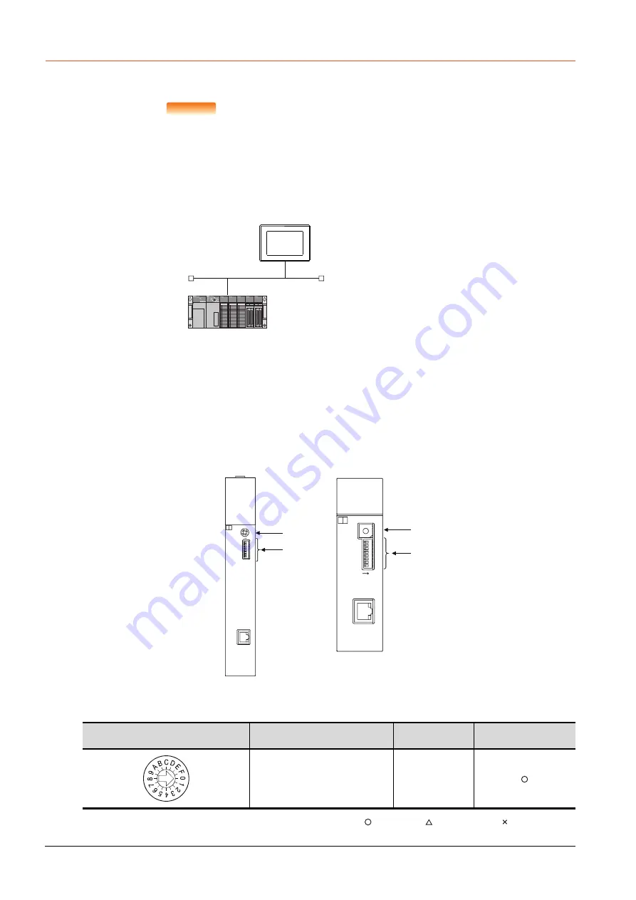
Connecting to Ethernet module (A Series)
This section describes the settings of the GOT and Ethernet module (A Series) in the following case of the system
configuration.
POINT
POINT
POINT
Ethernet module (A Series)
For details of the Ethernet module (A Series), refer to the following manual.
➠
For A Ethernet Interface Module User’s Manual
■1.
System configuration
*1
The Ethernet module is mounted on the base unit slot 0.
The Start I/O No. of the Ethernet module is set to "0".
*2
These setting items do not exist at the PLC side. However, the virtual values must be set on the GOT side.
➠
4. [Controller Setting] and [Ethernet] of GT Designer3
■2.
Switch settings of Ethernet module
Set the operation mode setting switch and exchange condition setting switch.
*1
The figure of AJ71E71N3-T and A1SJ71E71N3-T.
(1) Operation mode setting switch
: Necessary : As necessary : Not necessary
Operation mode setting switch
Description
Set value
Setting necessity at GOT
connection
Online
0
(fixed)
<GOT> (The settings other than the
following are set to the default)
*2
*2
*1
Network No.
: 1
PLC No.
: 1
IP address
: 192.168.3.18
Port No.
: 5001
Communication format : UDP (fixed)
Network No.
: 1 (virtual)
PLC No.
: 2 (virtual)
IP address
: 192.168.3.19
Port No.
: 5001
Communication format
: UDP(fixed)
<Ethernet module> (The settings other than the
following are set to the default)
A1SJ71E71N3-T
SW8
SW7
SW6
SW5
SW4
SW3
SW2
SW1
ON
10BASE-T
MODE
0:ONLINE
1:OFFLINE
2:TEST1
3:TEST2
4:TEST3
4
3 2
1
F
E
D
C
B
A
9
8 7
6 5
1SJ71E71N3-T
BSY
SW.ERR.
COM.ERR.
CPU R/W
TEST ERR.
TEST
A
RDY
RUN
BUF1
BUF2
BUF3
BUF4
BUF5
BUF6
BUF7
BUF8
0
10BASE-T
4
C
8
J71E71N3-T
RUN
BUF1
BUF2
BUF3
BUF4
BUF5
BUF6
BUF7
BUF8
RDY
BSY
SW.ERR.
COM.ERR.
CPU R/W
TEST
TEST ERR.
A
ON
0:ONLINE
4:TEST3
3:TEST2
2:TEST1
1:OFFLINE
MODE
SW8
SW7
SW6
SW5
SW4
SW3
SW2
SW1
0
(1)
(2)
A1SJ71E71N3-T, A1SJ71E71N-B5,
A1SJ71E71N-B2, A1SJ71E71N-T,
A1SJ71E71N-B5T, A1SJ71E71-B5-S3,
A1SJ71E71-B2-S3
AJ71E71N3-T, AJ71E71N-B5,
AJ71E71N-B2, AJ71E71N-T,
AJ71E71N-B5T, AJ71E71-S3
(1)
(2)
*1
*1
Содержание GOT2000 Series
Страница 2: ......
Страница 84: ......
Страница 432: ...6 58 6 6 Precautions ...
Страница 578: ...9 54 9 6 Precautions ...
Страница 726: ...12 84 12 5 Precautions ...
Страница 756: ......
Страница 822: ...14 66 14 4 Device Range that Can Be Set ...
Страница 918: ...15 96 15 7 Precautions ...
Страница 930: ...16 12 16 6 Precautions ...
Страница 963: ...MULTIPLE GOT CONNECTIONS 19 GOT MULTI DROP CONNECTION 19 1 20 MULTIPLE GT21 CONNECTION FUNCTION 20 1 ...
Страница 964: ......
Страница 1002: ...19 38 19 7 Precautions ...
Страница 1022: ...20 20 20 5 Precautions ...
Страница 1023: ...MULTI CHANNEL FUNCTION 21 MULTI CHANNEL FUNCTION 21 1 ...
Страница 1024: ......
Страница 1047: ...21 3 GOT Side Settings 21 23 21 MULTI CHANNEL FUNCTION Example Setting example for Ethernet connection 4 channels ...
Страница 1054: ...21 30 21 5 Multi channel Function Check Sheet ...
Страница 1055: ...FA TRANSPARENT FUNCTION 22 FA TRANSPARENT FUNCTION 22 1 ...
Страница 1056: ......
Страница 1223: ......


