


4 - 90
4.3 MELSEC Redundant Setting
*1 Pair number
Redundant CPU pair means the redundant CPUs (System A / System B) in the redundant system configuration.
Pair number is the number assigned to each redundant CPU pair.
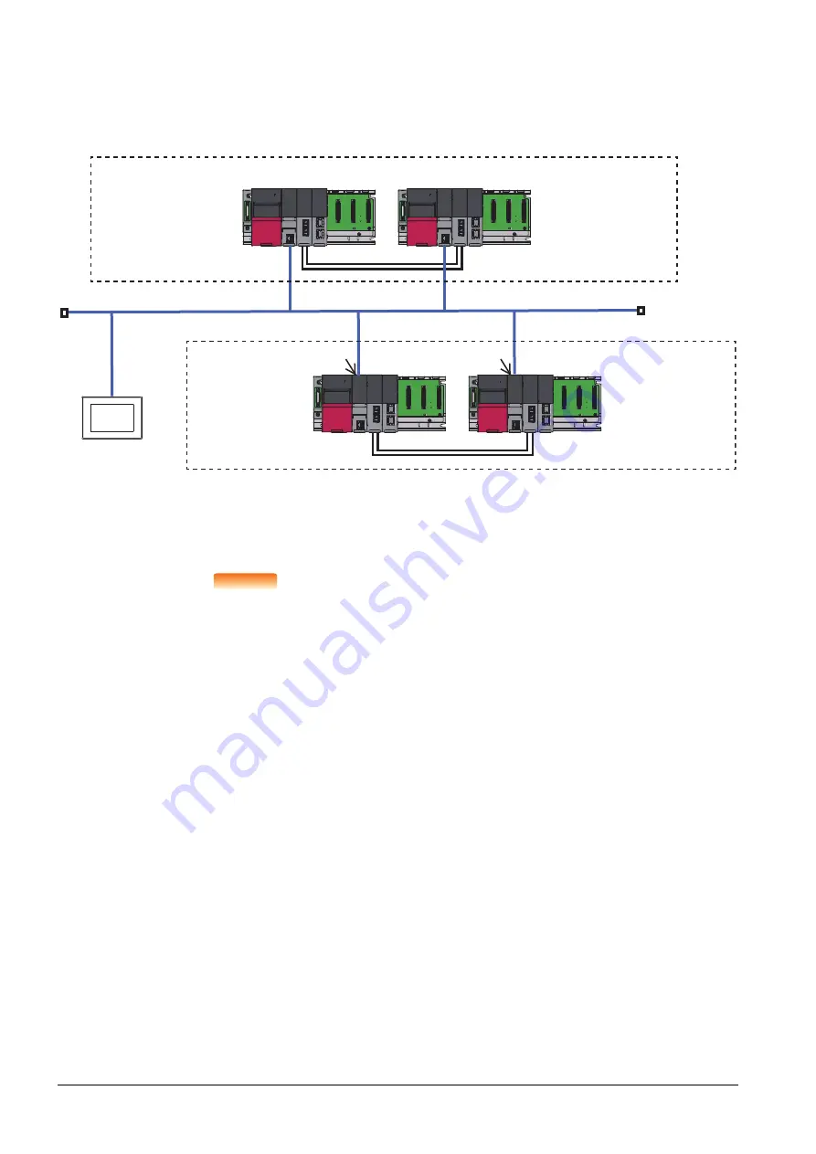
Example: Ethernet connection in the RCPU redundant system (Pair No. 1 and Pair No. 2)
POINT
POINT
POINT
Precautions for making MELSEC redundant setting
Pay attention to the following items when making the MELSEC redundant setting.
• Pairing of the last station No. and station No. 1 (Example: Station No. 64 and station No. 1) is
not allowed.
• Make sure that the QCPU in the station for which MELSEC redundant setting is made is a
redundant CPU.
If any of the QCPUs to which the MELSEC redundant setting is made is not a redundant CPU,
the GOT fails to automatically change the monitoring target to the control system when the
system is switched.
• When making the MELSEC redundant setting for MELSECNET/H, MELSECNET/10, or
Ethernet connections, check the station Nos. of network modules before the setting. If the
settings of the MELSEC redundant setting and the actual network module station Nos. are not
matched, the GOT fails to automatically change the monitoring target to the control system
when the system is switched.
• GOT supports the backup mode, which is the redundant mode of the RCPU redundant system,
and does not support the process mode and separate mode.
• GOT supports the backup mode, which is the operation mode of the QCPU redundant system,
and does not support the debug mode and separate mode.
GOT
1) Process CPU
2) Redundant function module
3) Tracking cable
4) CC-Link IE Filed Network Master/Local module
N/W No.: 1(virtual)
PC No.: 1(virtual)
IP address: 192.168.3.1
Port No.: 5006
N/W No.: 1(virtual)
PC No.: 2(virtual)
IP address: 192.168.3.2
Port No.: 5006
4)
2)
1)
1) 2) 4)
2) 4)
2) 4)
1)
1)
3)
3)
N/W No.: 1(virtual)
PC No.: 3(virtual)
IP address: 192.168.3.3
Port No.: 5006
N/W No.: 1(virtual)
PC No.: 4(virtual)
IP address: 192.168.3.4
Port No.: 5006
N/W No.: 1(virtual)
PC No.: 5(virtual)
IP address: 192.168.3.18
Port No.: 5001
Control system (system A)
Standby system (system B)
Control system
(system A)
Standby system (system B)
Ethernet
(Pair No.2)
(Pair No.1)
Содержание GOT2000 Series
Страница 2: ......
Страница 84: ......
Страница 432: ...6 58 6 6 Precautions ...
Страница 578: ...9 54 9 6 Precautions ...
Страница 726: ...12 84 12 5 Precautions ...
Страница 756: ......
Страница 822: ...14 66 14 4 Device Range that Can Be Set ...
Страница 918: ...15 96 15 7 Precautions ...
Страница 930: ...16 12 16 6 Precautions ...
Страница 963: ...MULTIPLE GOT CONNECTIONS 19 GOT MULTI DROP CONNECTION 19 1 20 MULTIPLE GT21 CONNECTION FUNCTION 20 1 ...
Страница 964: ......
Страница 1002: ...19 38 19 7 Precautions ...
Страница 1022: ...20 20 20 5 Precautions ...
Страница 1023: ...MULTI CHANNEL FUNCTION 21 MULTI CHANNEL FUNCTION 21 1 ...
Страница 1024: ......
Страница 1047: ...21 3 GOT Side Settings 21 23 21 MULTI CHANNEL FUNCTION Example Setting example for Ethernet connection 4 channels ...
Страница 1054: ...21 30 21 5 Multi channel Function Check Sheet ...
Страница 1055: ...FA TRANSPARENT FUNCTION 22 FA TRANSPARENT FUNCTION 22 1 ...
Страница 1056: ......
Страница 1223: ......