TM 11-6625-3071-14
NOTE
The CAL ENABLE Switch on the front
panel should not be in the CAL/ENABLE
position under normal use. It should only
be in that position to calibrate the
instrument.
3-66.
MISCELLANEOUS OPERATIONS
3-67.
Voltmeter Complete
3-68.
The Voltmeter Complete connector is a BNC
connector which outputs a signal at the end of the A/D
cycle. The signal is a negative going TTL compatible
pulse with a time period of approximately I
µ
S. The
Voltmeter Complete connector is located on the rear
panel.
3-69.
REMOTE OPERATION
3-70.
General
3-71.
The following paragraphs gives device
dependent information necessary to remotely operate the
3478A over the Hewlett-Packard Interface Bus (HP-IB).
Directions for mechanical interface connections to the
HP-IB are given in Section II of this manual. Familiarize
yourself with the front panel operation (local) before
attempting to use the multimeter in remote (HP-IB).
NOTE
HP-IB is Hewlett-Packard’s
implementation of IEEE Std. 488-1978,
"Standard Digital Interface for
Programmable Instrumentation" and
ANSI MC 1.1.
3-72.
A general description of the HP-IB is in this
manual’s Appendix A. Refer to the appendix for any non-
3478A related HP-IB information. It is assumed, in the
following paragraphs, that you are knowledgeable about
the HP-IB.
3-73.
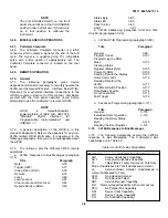
The following lists the different 3478A remote
operations.
a.
3478A Response to Bus Messages (paragraph
3-74).
Title
Paragraph
Data
3-76
Trigger (GET)
3-77
Clear (DCL or SDC)
3-78
Remote
3-79
Local
3-80
Local Lockout
3-81
Clear Lockout and Set Local
3-82
Require Service (SRQ)
3-83
Status Byte
3-85
Status Bit
3-89
Pass Control
3-90
Abort
3-91
b.
3478A Addressing (paragraph 3-92) and Talk-
Only Mode (paragraph 3-96).
c.
3478A HP-IB Programming (paragraph 3-98).
Title
Paragraph
General
3-99
Program Codes
3-101
Programming the SRQ
Mask
3-103
Clearing Status
Register (Status Byte)
3-105
Power-On SRQ
3-106
Sending Data to the Display
3-107
Home Commands
3-110
Reading Data from the
3478A
3-111
Front/Rear Switch Position
3-113
Data Ready Feature
3-114
Front Panel SRQ
3-115
Fast Trigger
3-116
d.
Advanced Programming (paragraph 3-117).
Title
Paragraph
General
3-118
Extended Ohms Operation
3-119
Reading the Binary Status
Byte
3-120
Reading the Error Register
3-121
3-74.
3478A Response to Bus Messages
3-75.
The following paragraphs explain the 3478A’s
response to Bus Messages. The multimeter’s Bus
capabilities are in Table 3-3.
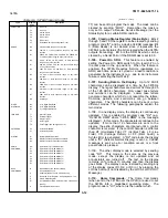
Table 3-3. 3478A’s Bus Capabilities
Mnemonic
Interface Function Name
SH1
Source Handshake Capability
AH 1
Acceptor Handshake Capability
T5
Talker (Basic Talker, Serial poll, Talk Only
Mode, Unaddressed to Talk if Addressed to Listen)
L4
Listener (Basic Listener, Unaddressed to
Listen if Addressed to Talk)
LEO
No Extended Listener
TEO
No Extended Talker
SR1
Service Request Capability
RL1
Remote/Local Capability with Local Lockout
PPO
No Parallel Poll Capability
DC1
Device Clear Capability
DT1
Device Trigger Capability
CO
No Controller Capability
3-8
Содержание 3478A
Страница 2: ...TM 11 6625 3071 14 A ...
Страница 4: ...TM 11 6625 3071 14 C D BLANK ...
Страница 12: ...TM 11 6625 3071 14 Table 1 1 Specification 1 2 ...
Страница 13: ...TM 11 6625 3071 14 Table 1 1 Specifications Cont 1 3 ...
Страница 14: ...TM 11 6625 3071 14 Table 1 1 Specifications Cont 1 4 ...
Страница 53: ...TM 11 6625 3071 14 1 ...
Страница 54: ...TM 11 6625 3071 14 2 ...
Страница 55: ...TM 11 6625 3071 14 3 ...
Страница 56: ...TM 11 6625 3071 14 4 ...
Страница 87: ...TM 11 6625 3071 14 3478A Figure 7 D 3 Flowchart B 7 D 5 ...
Страница 88: ...TM 11 6625 3071 14 3478A Figure 7 D 4 Flowchart C 7 D 6 ...
Страница 91: ...TM 11 6625 3071 14 3478A Figure 7 D 6 Flowchart D 7 D 9 ...
Страница 98: ...TM 11 6625 3071 14 3478A Figure 7 F 2 Simplified Schematic Of The Input Switching Circuitry 7 F 4 ...
Страница 111: ...TM 11 6625 3071 14 Figure 7 F 17 3478A Simplified Reference Circuitry 7 F 16 ...
Страница 122: ...TM 11 6625 3071 14 Table A 2 A 2 HP IB Worksheet A 4 ...
Страница 137: ...TM 11 6625 3071 14 Figure 7 D 2 Flow chart A 7 D 3 ...
Страница 139: ...TM 11 6625 3071 14 Figure 7 G 2 3478A Block Diagram 7 G 3 ...
Страница 140: ...TM 11 6625 3071 14 Component Locator for Input Circuitry and Ohms Current Source 7 G 4 ...
Страница 141: ...TM 11 6625 3071 14 Figure 7 G 3 Input Circuitry and Ohms Current Source 7 G 5 ...
Страница 142: ...TM 11 6625 3071 14 F G 6 ...
Страница 143: ...TM 11 6625 3071 14 2 Figure 7 G 4 AC to DC Converter 7 G 7 ...
Страница 144: ...TM 11 6625 3071 14 Component Locator for A D Converter and Control Logic 7 G 8 ...
Страница 145: ...TM 11 6625 3071 14 3 Figure 7 G 5 A D Converter and Control Logic 7 G 9 ...
Страница 146: ...TM 11 6625 3071 14 7 G 10 ...
Страница 147: ...TM 11 6625 3071 14 4 Figure 7 G 6 Power Supplies 7 G 11 7 G 12 blank ...
Страница 148: ......
Страница 149: ...PIN NO 057444 ...


