


3478A TM 11-6625-3071-14
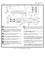
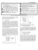
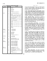
The 3478A HP-IB Address is displayed when the
Address key is pressed.
The Local key returns the 3478A to front panel
control from the REMOTE mode.
The 3478A features total electronic calibration. The
Cal key is used as part of that procedure See Section IV.
9 The range keys are used to select the proper
range for the measurement. Press any of the keys to
select the manual range mode. Note the M RNG
annunciator in the display The Auto/Man key will return
the meter to autorange.
10 (The "SHIFTED" functions of the range keys are
used to select alternate numbers of display digits
11 (The Rear Input Terminals are only used in the DC
Volts, AC Volts, and Ohms Functions. They are selected
with the Front/Rear Switch in the "in" position.
12 The External Trigger connector is used to externally
trigger the 3478A, when in the Single Trigger mode.
13 (HP-IB Connector.
14 (The Voltmeter Complete Connector outputs a pulse
after each measurement cycle.
15 The Fuse is 25OmA for the 100V and 120V
operation, or 125mA for the 220V and 240V operation.
16 The Option Label shows the instrument’s power
option.
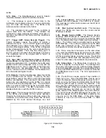
17 This switch selects the 3478A’s HP-IB Address,
the Power-On SRQ feature, and correct power line
frequency (50Hz-60Hz).
Figure 3-1. 3478A Front and Rear Panel Features (Cont’d)
characters to the left show the reading (e.g. + 12.3657
MVDC). An "OVLD" is displayed if the input is out of
range for the selected range and function.
3-12. Input Terminals
3-13. The 3478A has one set of Input Terminals on
the front panel and one set on the rear panel. The front
panel terminals consist of an "INPUT HI",
Ω
"INPUT LO",
"
Ω
SENSE HI",
Ω
SENSE LO", and "A" (Amps) terminal.
Except for the "A" terminal, the rear panel has the same
set of terminals. The two sets of terminals are selected
by the Front/Rear Switch (located on the front panel).
The front terminals are selected with the switch "out" and
the rear with the switch "in".
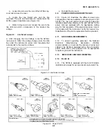
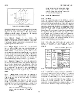
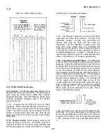
3-14. The INPUT HI and LO Terminals are used for
measuring dc volts, ac volts, and resistance in the 2-
Wire Ohms configuration. Refer to Figure 3-2 for a
typical connection. The
Ω
SENSE HI and
Ω
SENSE LO
Terminals (in conjunction with the INPUT Terminals) are
used in the 4-Wire Ohms configuration. Refer to Figure
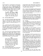
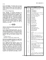
34 for a typical ohms connection. The A (Amps) Terminal
with the INPUT LO Terminal is used to measure ac or dc
current. Refer to Figure 3-3 for a typical current
connection.
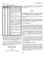
Figure 3-3.Typical Current Measurement Connection
3-15. Input Terminals Cleaning
3-16. The high input impedance of the 3478A requires
that the area surrounding the multimeter’s Input
Terminals (front or rear) must be free of leakage causing
paths (e.g. dirt, fingerprints, etc.). The paths can be
removed by using a soft cotton swab dipped in isopropyl
alcohol.
3-17. FRONT PANEL OPERATION
3-18. DC Volts Measurements
3-19. The 3478A is able to make dc volts
measurements from .1uV to 300V in five ranges: 30mV,
300mV, 3V, 30V, and 300V. All ranges are protected
from input voltages up to 450V peak. Select the DCV
Function for dc volts measurements by pressing the =v
button. 3-20. In the DC Volts Function, ranging is done
in the Input Circuitry of the 3478A. The result is that the
input to the A/D Converter (which changes the voltage to
digital information) has the same value in all ranges for
Figure 3-2. Typical Input Measurement Connection
3-3
Содержание 3478A
Страница 2: ...TM 11 6625 3071 14 A ...
Страница 4: ...TM 11 6625 3071 14 C D BLANK ...
Страница 12: ...TM 11 6625 3071 14 Table 1 1 Specification 1 2 ...
Страница 13: ...TM 11 6625 3071 14 Table 1 1 Specifications Cont 1 3 ...
Страница 14: ...TM 11 6625 3071 14 Table 1 1 Specifications Cont 1 4 ...
Страница 53: ...TM 11 6625 3071 14 1 ...
Страница 54: ...TM 11 6625 3071 14 2 ...
Страница 55: ...TM 11 6625 3071 14 3 ...
Страница 56: ...TM 11 6625 3071 14 4 ...
Страница 87: ...TM 11 6625 3071 14 3478A Figure 7 D 3 Flowchart B 7 D 5 ...
Страница 88: ...TM 11 6625 3071 14 3478A Figure 7 D 4 Flowchart C 7 D 6 ...
Страница 91: ...TM 11 6625 3071 14 3478A Figure 7 D 6 Flowchart D 7 D 9 ...
Страница 98: ...TM 11 6625 3071 14 3478A Figure 7 F 2 Simplified Schematic Of The Input Switching Circuitry 7 F 4 ...
Страница 111: ...TM 11 6625 3071 14 Figure 7 F 17 3478A Simplified Reference Circuitry 7 F 16 ...
Страница 122: ...TM 11 6625 3071 14 Table A 2 A 2 HP IB Worksheet A 4 ...
Страница 137: ...TM 11 6625 3071 14 Figure 7 D 2 Flow chart A 7 D 3 ...
Страница 139: ...TM 11 6625 3071 14 Figure 7 G 2 3478A Block Diagram 7 G 3 ...
Страница 140: ...TM 11 6625 3071 14 Component Locator for Input Circuitry and Ohms Current Source 7 G 4 ...
Страница 141: ...TM 11 6625 3071 14 Figure 7 G 3 Input Circuitry and Ohms Current Source 7 G 5 ...
Страница 142: ...TM 11 6625 3071 14 F G 6 ...
Страница 143: ...TM 11 6625 3071 14 2 Figure 7 G 4 AC to DC Converter 7 G 7 ...
Страница 144: ...TM 11 6625 3071 14 Component Locator for A D Converter and Control Logic 7 G 8 ...
Страница 145: ...TM 11 6625 3071 14 3 Figure 7 G 5 A D Converter and Control Logic 7 G 9 ...
Страница 146: ...TM 11 6625 3071 14 7 G 10 ...
Страница 147: ...TM 11 6625 3071 14 4 Figure 7 G 6 Power Supplies 7 G 11 7 G 12 blank ...
Страница 148: ......
Страница 149: ...PIN NO 057444 ...


