TM 11-6625-3071-14
3478A
4-82. Calibration Messages
4-83. When calibrating the 3478A, certain messages
may be displayed by the multimeter. The following lists
the messages and also gives information on what to do if
a certain message is displayed.
a. UNCALIBRATED - When this message is
displayed, calibrate the 3478A. The message normally
shows up during a Self-Test routine and indicates that
the calibration RAM has an incorrect checksum.
b. ENABLE CAL - This message shows that the front
panel CAL ENABLE switch is not in the enable position
(the slot of the switch is horizontal) when attempting to
calibrate the multimeter. Make sure the switch is in the
correct position, when attempting to calibrate.
c. CAL ABORTED - The 3478A displays this message
when an invalid pushbutton was pressed (e.g., the SRQ
button), an overload is detected, or an A/D error is
detected. This can only be true during calibration (i.e.,
after pressing the CAL button). Make sure the correct
button is pressed, the calibration source is at the correct
value, and the 3478A is operating correctly.
d. VALUE ERROR - This message is displayed when
the following conditions are true.
1. A zero calibration is attempted and the 3478A
reads a value of greater than ± 1000 counts (e.g.
reads I ohm on the 30 ohm range).
2. A full scale or 1/3 scale (gain) calibration is
attempted in the DC Volts Function with a negative
input voltage. Make sure the input voltage is always
positive, when calibrating the DC Volts Function.
3. A full scale or 1/3 scale calibration is attempted
outside the available range (greater than ±7%). For
example, an attempt is made to calibrate the 3478A
with a value of +3.21V or +2.79V (greater than :t:7%).
Make sure the calibration source is within the
specified range, when calibrating at full scale and 1/3
scale.
4. An AC Volts calibration is attempted when the
applied calibration source is other than 3V ac. Make
sure the calibration source is correct (3V at 1KHz).
e. ACI VAL ERR - The multimeter displays this
message when it is unable to calculate an AC Current
calibration constant, after doing the AC Volts Calibration.
This condition can exist if the calibration constant for the
DC Current Function is invalid. Make sure the 300mA
and 3A Range in the DC Current Function is correctly
calibrated.
f. CAL FINISHED - A calibration cycle has been
successfully completed.
g. CALIBRATING - Calibration in progress.
4-84. Calibration Procedures
4-85. Each step in the procedures and the procedures
themselves must be done in the order they are given.
Each procedure has two parts, Calibration and
Performance Test. The Performance Test part can be
ignored, if so desired. Since, after calibration, the 3478A
will meet its full scale 24 Hour limits, the Performance
Test for full scale (or in some cases 1/3 scale) and zero
inputs are not included. This is because the 3478A is
normally calibrated using full scale (or 1/3 scale) and
zero inputs. The Calibration and Performance Test
Procedures are separated as follows:
a. DC Volts Calibration and Test- paragraph 4-86.
b. DC Current Calibration and Test - paragraph 4-90.
c. AC Volts Calibration and Test - paragraph 4-94.
d. AC Current Calibration and Test - paragraph 4-99.
e. Ohms Calibration and Test - paragraph 4-103.
4-86. DC Volts Calibration and Teat
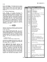
4-87. Refer to Table 4-8 for the DC Volts Calibration
Signals, Performance Test Signals, and Performance
Test Limits. Each step in the table is shown in
parenthesis in the procedure. Unless otherwise noted,
the calibration and test signals are applied to the 3478A's
HI and LO INPUT Terminals.
4-88. Equipment Required. The following is the
required test equipment for the DC Volts Calibration and
Test.
Digital Voltmeter (-hp- Model 3456A)
Table 4-8. DC Volts Calibration and Test
4-13
Содержание 3478A
Страница 2: ...TM 11 6625 3071 14 A ...
Страница 4: ...TM 11 6625 3071 14 C D BLANK ...
Страница 12: ...TM 11 6625 3071 14 Table 1 1 Specification 1 2 ...
Страница 13: ...TM 11 6625 3071 14 Table 1 1 Specifications Cont 1 3 ...
Страница 14: ...TM 11 6625 3071 14 Table 1 1 Specifications Cont 1 4 ...
Страница 53: ...TM 11 6625 3071 14 1 ...
Страница 54: ...TM 11 6625 3071 14 2 ...
Страница 55: ...TM 11 6625 3071 14 3 ...
Страница 56: ...TM 11 6625 3071 14 4 ...
Страница 87: ...TM 11 6625 3071 14 3478A Figure 7 D 3 Flowchart B 7 D 5 ...
Страница 88: ...TM 11 6625 3071 14 3478A Figure 7 D 4 Flowchart C 7 D 6 ...
Страница 91: ...TM 11 6625 3071 14 3478A Figure 7 D 6 Flowchart D 7 D 9 ...
Страница 98: ...TM 11 6625 3071 14 3478A Figure 7 F 2 Simplified Schematic Of The Input Switching Circuitry 7 F 4 ...
Страница 111: ...TM 11 6625 3071 14 Figure 7 F 17 3478A Simplified Reference Circuitry 7 F 16 ...
Страница 122: ...TM 11 6625 3071 14 Table A 2 A 2 HP IB Worksheet A 4 ...
Страница 137: ...TM 11 6625 3071 14 Figure 7 D 2 Flow chart A 7 D 3 ...
Страница 139: ...TM 11 6625 3071 14 Figure 7 G 2 3478A Block Diagram 7 G 3 ...
Страница 140: ...TM 11 6625 3071 14 Component Locator for Input Circuitry and Ohms Current Source 7 G 4 ...
Страница 141: ...TM 11 6625 3071 14 Figure 7 G 3 Input Circuitry and Ohms Current Source 7 G 5 ...
Страница 142: ...TM 11 6625 3071 14 F G 6 ...
Страница 143: ...TM 11 6625 3071 14 2 Figure 7 G 4 AC to DC Converter 7 G 7 ...
Страница 144: ...TM 11 6625 3071 14 Component Locator for A D Converter and Control Logic 7 G 8 ...
Страница 145: ...TM 11 6625 3071 14 3 Figure 7 G 5 A D Converter and Control Logic 7 G 9 ...
Страница 146: ...TM 11 6625 3071 14 7 G 10 ...
Страница 147: ...TM 11 6625 3071 14 4 Figure 7 G 6 Power Supplies 7 G 11 7 G 12 blank ...
Страница 148: ......
Страница 149: ...PIN NO 057444 ...


