


TM 11-6625-3071-14
3478A
4-47. PERFORMANCE TEST
4-48. The Performance Test is separated into five main
tests: DC Volts, DC Current, AC Volts, AC Current, and
Ohms. Each step in the tests and the tests themselves
should be done in the order they are given, starting with
the DC Volts Test. Allow at least a 1 hour warm-up time.
If the 3478A has been on for less time, inaccuracies can
result. The Performance Test is separated into the
following tests.
a. DC Volts Test - paragraph 4-49.
b. DC Current Test - paragraph 4-54.
c. AC Volts Test - paragraph 4-59.
d. AC Current Test - paragraph 4-64.
e. Ohms Test - paragraph 4-69.
NOTE
Leakage paths on the 3478A ’s front panel
area surrounding the input terminals can
affect the instrument’s input impedance.
The paths can be removed by using a soft
cotton swab dipped in isopropyl alcohol.
4-49. DC Volts Test
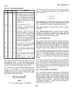
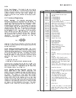
4-50. The DC Volts Test limits are printed on the DC
Volts Test Card and in Table 4-3. The instrument set-up
information is also printed on the test card. Each step on
the test card corresponds to a step in the test procedure.
Because of this, each step number on the test card is
shown in parenthesis (e.g., Step #1.) in the procedure.
4-51. Unless otherwise specified, all test signals are
applied to the 3478A’s HI and LO INPUT Terminals.
4-52. Equipment Required. The following is the
required test equipment for the DC Volts Test.
Digital Voltmeter (-hp- Model 3456A)
DC Volts Standard (Systron Donner Model M107)
4-53. Test Procedure. After the 3478A has been
warmed up for at least one hour, do the following:
a. (Step #1.) Reset the 3478A by pressing the blue
Shift button and then the SGL/TRIG (TEST/RESET)
button.
NOTE
Resetting the 3478A, automatically places
the instrument into the DC Volts Function,
Autorange, Internal Trigger, and 5 Digits
Display mode.
b. (Step #2.) Short the 3478A’s HI and LO INPUT
Terminals. The instrument should now be on the 30mV
Range.
c. Record the displayed reading on the Test Card and
make sure the reading is within the limits shown on the
Test Card and in Table 4-3.
d. (Step #3, 4, 5, and 6.) Set the 3478A to the 300mV,
3V, 30V, and 300V Range by pressing the Uprange
button once for each range. Record and make sure the
reading on each range is within the specified limits. If
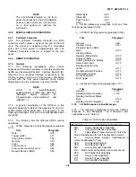
Table 4-3. DC Volts Test Limits
4-5
Содержание 3478A
Страница 2: ...TM 11 6625 3071 14 A ...
Страница 4: ...TM 11 6625 3071 14 C D BLANK ...
Страница 12: ...TM 11 6625 3071 14 Table 1 1 Specification 1 2 ...
Страница 13: ...TM 11 6625 3071 14 Table 1 1 Specifications Cont 1 3 ...
Страница 14: ...TM 11 6625 3071 14 Table 1 1 Specifications Cont 1 4 ...
Страница 53: ...TM 11 6625 3071 14 1 ...
Страница 54: ...TM 11 6625 3071 14 2 ...
Страница 55: ...TM 11 6625 3071 14 3 ...
Страница 56: ...TM 11 6625 3071 14 4 ...
Страница 87: ...TM 11 6625 3071 14 3478A Figure 7 D 3 Flowchart B 7 D 5 ...
Страница 88: ...TM 11 6625 3071 14 3478A Figure 7 D 4 Flowchart C 7 D 6 ...
Страница 91: ...TM 11 6625 3071 14 3478A Figure 7 D 6 Flowchart D 7 D 9 ...
Страница 98: ...TM 11 6625 3071 14 3478A Figure 7 F 2 Simplified Schematic Of The Input Switching Circuitry 7 F 4 ...
Страница 111: ...TM 11 6625 3071 14 Figure 7 F 17 3478A Simplified Reference Circuitry 7 F 16 ...
Страница 122: ...TM 11 6625 3071 14 Table A 2 A 2 HP IB Worksheet A 4 ...
Страница 137: ...TM 11 6625 3071 14 Figure 7 D 2 Flow chart A 7 D 3 ...
Страница 139: ...TM 11 6625 3071 14 Figure 7 G 2 3478A Block Diagram 7 G 3 ...
Страница 140: ...TM 11 6625 3071 14 Component Locator for Input Circuitry and Ohms Current Source 7 G 4 ...
Страница 141: ...TM 11 6625 3071 14 Figure 7 G 3 Input Circuitry and Ohms Current Source 7 G 5 ...
Страница 142: ...TM 11 6625 3071 14 F G 6 ...
Страница 143: ...TM 11 6625 3071 14 2 Figure 7 G 4 AC to DC Converter 7 G 7 ...
Страница 144: ...TM 11 6625 3071 14 Component Locator for A D Converter and Control Logic 7 G 8 ...
Страница 145: ...TM 11 6625 3071 14 3 Figure 7 G 5 A D Converter and Control Logic 7 G 9 ...
Страница 146: ...TM 11 6625 3071 14 7 G 10 ...
Страница 147: ...TM 11 6625 3071 14 4 Figure 7 G 6 Power Supplies 7 G 11 7 G 12 blank ...
Страница 148: ......
Страница 149: ...PIN NO 057444 ...


