TM 11-6625-3071-14
SECTION III
OPERATION
3-1.
INTRODUCTION
3-2.
This section has the information and
instructions for the operation of the 3478A Multimeter,
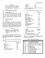
showing front panel and remote operation. The
information is an abbreviated description of the operation
and is written for a Service Trained Person, rather than
an Operator. For more complete operating instructions,
refer to the 3478A’s Operators Manual. To familiarize
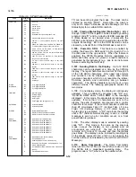
yourself with the front and rear panel features or for a
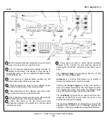
review of instrument operations, refer to Figure 3-1.
3-3.
The Operation Section is separated into the
following major areas: General Information, Front Panel
Operation, Shifted Operation, Miscellaneous Operation,
and Remote Operation (HP-IB). It is suggested that you
read the Remote Operation Chapters last, since you
need to know the other operations to understand the
remote operations. The major areas are as follows:
a.
General Information - paragraph 3-4.
Title
Paragraph
AC Power Operation
3-5
Turn-On
3-7
Display
3-10
Input Terminals
3-12
Input Terminals Cleaning
3-15
b.
Front Panel Operation - paragraph 3-17.
Title
Paragraph
DC Volts Measurements
3-18
AC Volts Measurements
3-22
Resistance Measurements
3-26
DC Current Measurements
3-30
AC Current Measurements
3-34
Ranging
3-38
Triggering
3-43
c.
Shifted Operation - paragraph 3-50.
Title
Paragraph
Number Of Digits Displayed
3-54
Autozero
3-57
Self-Test/Reset Operation
3-60
Calibration
3-63
d.
Miscellaneous Operation - paragraph 3-66.
Title
Paragraph
Voltmeter Complete
3-67
e.
Remote Operation - paragraph 3-69.
Title
Paragraph
General ...................................... 3-70
3478A Response to Bus
Messages................................... 3-74
3478A Addressing...................... 3-92
Talk-Only Mode (No
Controller) .................................. 3-96
3478A HP-IB Programming ....... 3-98
Advanced programming ............. 3-117
3-4.
GENERAL INFORMATION
3-5.
AC Power Operation
3-6.
Before connecting ac power to the 3478A, make
sure the power source matches the power requirement
of the multimeter (as marked on the rear panel). If the
instrument is incompatible with the power source, refer to
Section II of this manual for power requirement
modification.
3-7.
Turn-On
3-8.
When the 3478A is first turned on, the
multimeter goes through an Internal Test routine. During
the test, a certain message or characters may be
displayed for abour l/4 second. When the test is
completed and the 3478A passes the test, the 3478A’s
remote (HP-IB) address will be displayed for about one
second. The address is displayed as "HPIB ADRS, dd",
where "dd" is the address code of the instrument. If the
Self-Test fails, refer to Section VII of this manual for
troubleshooting information. For more information on the
Self-Test, refer to paragraph 3-58.
3-9.
Once the Self-Test is completed, the 3478A
goes to its turn-on state which is:
FUNCTION .............................................DCV
RANGE ...................................................AUTO
TRIGGER ...............................................INTERNAL
AUTOZERO ............................................ON
NUMBER OF DIGITS DISPLAYED.........5
3-10.
Display
3-11.
The Display is a 12 character alphanumeric
Liquid Crystal Display (LCD) with 12 annunciators. The
display is normally used to show readings, however, the
display can also show alphanumeric messages (sent
remotely). The four characters to the right show the
function (and to a certain extent, the range) and the 8
3-1
Содержание 3478A
Страница 2: ...TM 11 6625 3071 14 A ...
Страница 4: ...TM 11 6625 3071 14 C D BLANK ...
Страница 12: ...TM 11 6625 3071 14 Table 1 1 Specification 1 2 ...
Страница 13: ...TM 11 6625 3071 14 Table 1 1 Specifications Cont 1 3 ...
Страница 14: ...TM 11 6625 3071 14 Table 1 1 Specifications Cont 1 4 ...
Страница 53: ...TM 11 6625 3071 14 1 ...
Страница 54: ...TM 11 6625 3071 14 2 ...
Страница 55: ...TM 11 6625 3071 14 3 ...
Страница 56: ...TM 11 6625 3071 14 4 ...
Страница 87: ...TM 11 6625 3071 14 3478A Figure 7 D 3 Flowchart B 7 D 5 ...
Страница 88: ...TM 11 6625 3071 14 3478A Figure 7 D 4 Flowchart C 7 D 6 ...
Страница 91: ...TM 11 6625 3071 14 3478A Figure 7 D 6 Flowchart D 7 D 9 ...
Страница 98: ...TM 11 6625 3071 14 3478A Figure 7 F 2 Simplified Schematic Of The Input Switching Circuitry 7 F 4 ...
Страница 111: ...TM 11 6625 3071 14 Figure 7 F 17 3478A Simplified Reference Circuitry 7 F 16 ...
Страница 122: ...TM 11 6625 3071 14 Table A 2 A 2 HP IB Worksheet A 4 ...
Страница 137: ...TM 11 6625 3071 14 Figure 7 D 2 Flow chart A 7 D 3 ...
Страница 139: ...TM 11 6625 3071 14 Figure 7 G 2 3478A Block Diagram 7 G 3 ...
Страница 140: ...TM 11 6625 3071 14 Component Locator for Input Circuitry and Ohms Current Source 7 G 4 ...
Страница 141: ...TM 11 6625 3071 14 Figure 7 G 3 Input Circuitry and Ohms Current Source 7 G 5 ...
Страница 142: ...TM 11 6625 3071 14 F G 6 ...
Страница 143: ...TM 11 6625 3071 14 2 Figure 7 G 4 AC to DC Converter 7 G 7 ...
Страница 144: ...TM 11 6625 3071 14 Component Locator for A D Converter and Control Logic 7 G 8 ...
Страница 145: ...TM 11 6625 3071 14 3 Figure 7 G 5 A D Converter and Control Logic 7 G 9 ...
Страница 146: ...TM 11 6625 3071 14 7 G 10 ...
Страница 147: ...TM 11 6625 3071 14 4 Figure 7 G 6 Power Supplies 7 G 11 7 G 12 blank ...
Страница 148: ......
Страница 149: ...PIN NO 057444 ...


